- 您現(xiàn)在的位置:買賣IC網(wǎng) > PDF目錄370261 > FW82815 Controller Miscellaneous - Datasheet Reference PDF資料下載
參數(shù)資料
| 型號: | FW82815 |
| 英文描述: | Controller Miscellaneous - Datasheet Reference |
| 中文描述: | 控制器雜項-數(shù)據(jù)表參考 |
| 文件頁數(shù): | 55/172頁 |
| 文件大?。?/td> | 795K |
| 代理商: | FW82815 |
第1頁第2頁第3頁第4頁第5頁第6頁第7頁第8頁第9頁第10頁第11頁第12頁第13頁第14頁第15頁第16頁第17頁第18頁第19頁第20頁第21頁第22頁第23頁第24頁第25頁第26頁第27頁第28頁第29頁第30頁第31頁第32頁第33頁第34頁第35頁第36頁第37頁第38頁第39頁第40頁第41頁第42頁第43頁第44頁第45頁第46頁第47頁第48頁第49頁第50頁第51頁第52頁第53頁第54頁當前第55頁第56頁第57頁第58頁第59頁第60頁第61頁第62頁第63頁第64頁第65頁第66頁第67頁第68頁第69頁第70頁第71頁第72頁第73頁第74頁第75頁第76頁第77頁第78頁第79頁第80頁第81頁第82頁第83頁第84頁第85頁第86頁第87頁第88頁第89頁第90頁第91頁第92頁第93頁第94頁第95頁第96頁第97頁第98頁第99頁第100頁第101頁第102頁第103頁第104頁第105頁第106頁第107頁第108頁第109頁第110頁第111頁第112頁第113頁第114頁第115頁第116頁第117頁第118頁第119頁第120頁第121頁第122頁第123頁第124頁第125頁第126頁第127頁第128頁第129頁第130頁第131頁第132頁第133頁第134頁第135頁第136頁第137頁第138頁第139頁第140頁第141頁第142頁第143頁第144頁第145頁第146頁第147頁第148頁第149頁第150頁第151頁第152頁第153頁第154頁第155頁第156頁第157頁第158頁第159頁第160頁第161頁第162頁第163頁第164頁第165頁第166頁第167頁第168頁第169頁第170頁第171頁第172頁
82815 GMCH
R
Datasheet
55
3.4.17.
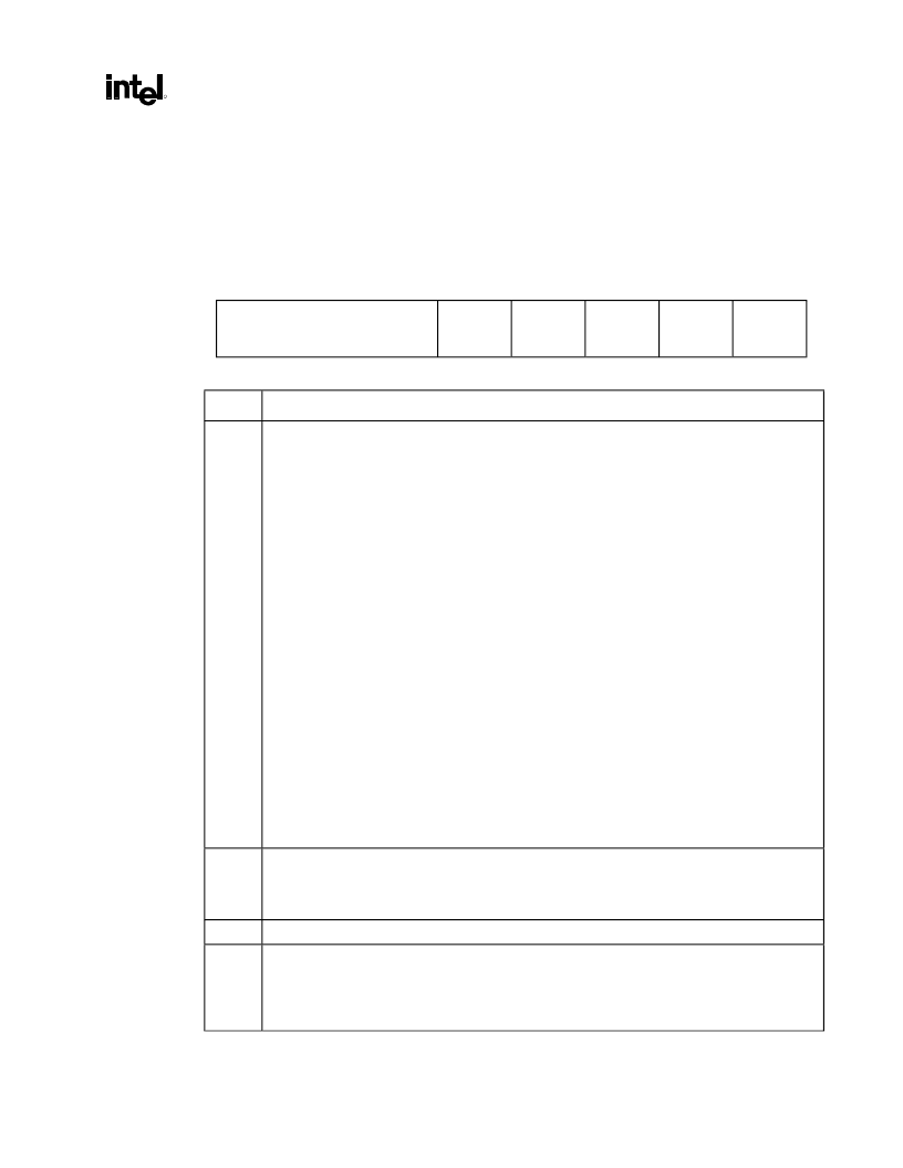
DRAMT—DRAM Timing Register (Device 0)
Address Offset:
Default Value:
Access:
Size:
53h
00h
Read/Write
8 bits
This register controls the operating mode and the timing of the DRAM Controller.
7
5
4
3
2
1
0
SDRAM Mode Select
DRAM
Cycle
Time
Intel
Reserved
CAS#
Latency
SDRAM
RAS# to
CAS# Dly
SDRAM
RAS#
Precharge
Bit
Description
7:5
SDRAM Mode Select (SMS).
These bits select the operational mode of the GMCH DRAM interface.
The special modes are intended for initialization at power up.
000 =
DRAM in Self-Refresh Mode
, Refresh Disabled (Default)
001 =
Normal
Operation, 100 MHz System memory – Refresh interval 15.6 uSec
133 MHz System memory – Refresh interval 11.7 uSec
010 =
Normal
Operation, 100 MHz System memory – Refresh interval 7.8
133 MHz System memory – Refresh interval 5.85 uSec
011 =
Normal
Operation, 100 MHz System memory – Refresh interval 1.28 uSec
133 MHz System memory – Refresh interval 0.96 uSec
100 =
NOP Command Enable.
In this mode all processor cycles to SDRAM result in a NOP
Command on the SDRAM interface.
101 =
All Banks Precharge Enable.
In this mode all processor cycles to SDRAM result in an All
Banks Precharge Command on the SDRAM interface.
110 =
Mode Register Set Enable.
In this mode all processor cycles to SDRAM result in a mode
register set command on the SDRAM interface. The Command is driven on the MA[12:0] lines.
MA[2:0] must always be driven to 010 for burst of 4 mode. MA3 must be driven to 1 for
interleave wrap type. MA4 needs to be driven to the value programmed in the CAS# Latency bit.
MA[6:5] should always be driven to 01. MA[12:7] must be driven to 00000. BIOS must calculate
and drive the correct host address for each row of memory such that the correct command is
driven on the MA[12:0] lines.
Note that MAB[7:4]# are inverted from MAA[7:4]; BIOS must account for this.
111 =
CBR Enable.
In this mode all processor cycles to SDRAM result in a CBR cycle on the SDRAM
interface.
4
DRAM Cycle Time (DCT).
This bit controls the number of SCLKs for an access cycle.
0 = Tras = 5 SCLKs and Trc = 7 SCLKs (Default)
1 = Tras = 7 SCLKs and Trc = 9 SCLKs.
3
Intel Reserved.
2
CAS# Latency (CL).
This bit controls the number of CLKs between when a read command is sampled
by the SDRAMs and when GMCH samples read data from the SDRAMs.
0 = CAS# latency is 3 SCLKs.
1 = CAS# latency is 2 SCLKs.
相關(guān)PDF資料 |
PDF描述 |
|---|---|
| FWA-25A10F | Fuse |
| FWA-30A10F | Fuse |
| FWA-35A21F | Fuse |
| FWA-40A21F | Fuse |
| FWA-45A21F | Fuse |
相關(guān)代理商/技術(shù)參數(shù) |
參數(shù)描述 |
|---|---|
| FW82815 S L5NQ | 制造商:Intel 功能描述:Graphics and Memory Controller Hub 544-Pin BGA |
| FW82815EM S L4MP | 制造商:Intel 功能描述:GRAPHICS AND MEMORY CONTROLLER HUB (GMCH2-M) |
| FW82815SL5NQ | 制造商:Intel 功能描述: |
| FW828201CA | 制造商:未知廠家 制造商全稱:未知廠家 功能描述:Controller Miscellaneous - Datasheet Reference |
| FW82840 S L3TA | 制造商:Intel 功能描述:Memory Controller Hub 544-Pin BGA |
發(fā)布緊急采購,3分鐘左右您將得到回復。