- 您現(xiàn)在的位置:買賣IC網(wǎng) > PDF目錄370261 > FW82815 Controller Miscellaneous - Datasheet Reference PDF資料下載
參數(shù)資料
| 型號: | FW82815 |
| 英文描述: | Controller Miscellaneous - Datasheet Reference |
| 中文描述: | 控制器雜項-數(shù)據(jù)表參考 |
| 文件頁數(shù): | 113/172頁 |
| 文件大?。?/td> | 795K |
| 代理商: | FW82815 |
第1頁第2頁第3頁第4頁第5頁第6頁第7頁第8頁第9頁第10頁第11頁第12頁第13頁第14頁第15頁第16頁第17頁第18頁第19頁第20頁第21頁第22頁第23頁第24頁第25頁第26頁第27頁第28頁第29頁第30頁第31頁第32頁第33頁第34頁第35頁第36頁第37頁第38頁第39頁第40頁第41頁第42頁第43頁第44頁第45頁第46頁第47頁第48頁第49頁第50頁第51頁第52頁第53頁第54頁第55頁第56頁第57頁第58頁第59頁第60頁第61頁第62頁第63頁第64頁第65頁第66頁第67頁第68頁第69頁第70頁第71頁第72頁第73頁第74頁第75頁第76頁第77頁第78頁第79頁第80頁第81頁第82頁第83頁第84頁第85頁第86頁第87頁第88頁第89頁第90頁第91頁第92頁第93頁第94頁第95頁第96頁第97頁第98頁第99頁第100頁第101頁第102頁第103頁第104頁第105頁第106頁第107頁第108頁第109頁第110頁第111頁第112頁當(dāng)前第113頁第114頁第115頁第116頁第117頁第118頁第119頁第120頁第121頁第122頁第123頁第124頁第125頁第126頁第127頁第128頁第129頁第130頁第131頁第132頁第133頁第134頁第135頁第136頁第137頁第138頁第139頁第140頁第141頁第142頁第143頁第144頁第145頁第146頁第147頁第148頁第149頁第150頁第151頁第152頁第153頁第154頁第155頁第156頁第157頁第158頁第159頁第160頁第161頁第162頁第163頁第164頁第165頁第166頁第167頁第168頁第169頁第170頁第171頁第172頁
82815 GMCH
R
Datasheet
113
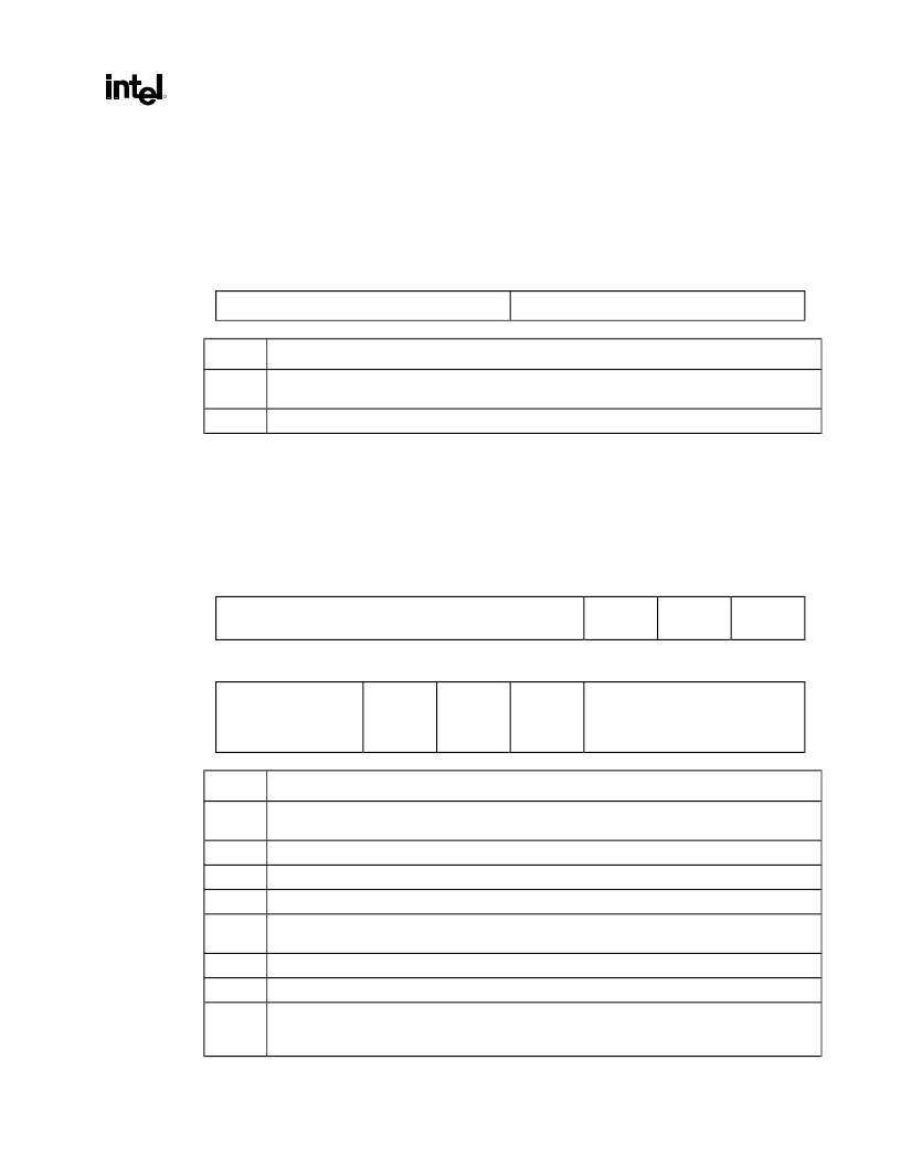
3.6.23.
PM_CAPID—Power Management Capabilities ID Register
(Device 2)
Address Offset:
DCh
DDh
Default Value:
0001h
Access:
Read Only
Size:
16 bits
15
8
7
0
NEXT_PTR
CAP_ID
Bits
Description
15:8
Next Pointer (NEXT_PTR).
This contains a pointer to next item in the capabilities list. This the final
capability in the list and must be set to 00h.
7:0
Capability Identificaiton (CAP_ID).
SIG defines this ID is 01h for power management.
3.6.24.
PM_CAP—Power Management Capabilities Register (Device 2)
Address Offset:
DEh
DFh
Default Value:
0022h
Access:
Read Only
Size:
16 bits
15
11
10
9
8
PME Support (HW=0)
D2
(HW=0)
D1
(HW=0)
Reserved
7
6
5
4
3
2
0
Reserved
Dev
Specific
Init
(HW=1)
Aux Pwr
Src
(HW=0)
PME
Clock
(HW=0)
Version
Bits
Description
15:11
PME Support.
This field indicates the power states in which the GMCH may assert PME#. Hardwired
to 0 to indicate that the GMCH does not assert the PME# signal.
10
D2.
Hardwired to 0 to indicate D2 power management state is not supported.
9
D1.
Hardwired to0 to indicate that D1 power management state is NOT supported.
8:6
Reserved. Read as 0s.
5
Device Specific Initialization (DSI).
Hardwired to 1 to indicate that special initialization of the GMCH
is required before generic class device driver is to use it.
4
Auxiliary Power Source.
Hardwired to 0.
3
PME Clock.
Hardwired to 0 to indicate the GMCH does not support PME# generation.
2:0
Version.
Hardwired to 010b to indicate there are 4 bytes of power management registers
implemented and that this device complies with revision 1.1 of the
PCI Power Management Interface
Specification
.
相關(guān)PDF資料 |
PDF描述 |
|---|---|
| FWA-25A10F | Fuse |
| FWA-30A10F | Fuse |
| FWA-35A21F | Fuse |
| FWA-40A21F | Fuse |
| FWA-45A21F | Fuse |
相關(guān)代理商/技術(shù)參數(shù) |
參數(shù)描述 |
|---|---|
| FW82815 S L5NQ | 制造商:Intel 功能描述:Graphics and Memory Controller Hub 544-Pin BGA |
| FW82815EM S L4MP | 制造商:Intel 功能描述:GRAPHICS AND MEMORY CONTROLLER HUB (GMCH2-M) |
| FW82815SL5NQ | 制造商:Intel 功能描述: |
| FW828201CA | 制造商:未知廠家 制造商全稱:未知廠家 功能描述:Controller Miscellaneous - Datasheet Reference |
| FW82840 S L3TA | 制造商:Intel 功能描述:Memory Controller Hub 544-Pin BGA |
發(fā)布緊急采購,3分鐘左右您將得到回復(fù)。