- 您現(xiàn)在的位置:買賣IC網(wǎng) > PDF目錄298813 > AD6652XBC (ANALOG DEVICES INC) SPECIALTY TELECOM CIRCUIT, PBGA256 PDF資料下載
參數(shù)資料
| 型號(hào): | AD6652XBC |
| 廠商: | ANALOG DEVICES INC |
| 元件分類: | 通信及網(wǎng)絡(luò) |
| 英文描述: | SPECIALTY TELECOM CIRCUIT, PBGA256 |
| 封裝: | 17 X 17 MM, MINI, BGA-256 |
| 文件頁數(shù): | 33/76頁 |
| 文件大?。?/td> | 1802K |
| 代理商: | AD6652XBC |
第1頁第2頁第3頁第4頁第5頁第6頁第7頁第8頁第9頁第10頁第11頁第12頁第13頁第14頁第15頁第16頁第17頁第18頁第19頁第20頁第21頁第22頁第23頁第24頁第25頁第26頁第27頁第28頁第29頁第30頁第31頁第32頁當(dāng)前第33頁第34頁第35頁第36頁第37頁第38頁第39頁第40頁第41頁第42頁第43頁第44頁第45頁第46頁第47頁第48頁第49頁第50頁第51頁第52頁第53頁第54頁第55頁第56頁第57頁第58頁第59頁第60頁第61頁第62頁第63頁第64頁第65頁第66頁第67頁第68頁第69頁第70頁第71頁第72頁第73頁第74頁第75頁第76頁
Preliminary Technical Data
AD6652
Rev. PrC | Page 39 of 76
op.
terest. The AGC strives to maintain a constant mean
a
d a constant gain can be provided
throu
the AGC gain multiplier.
urces of error may be introduced by the AGC function:
ow, overflow, and modulation. Underflow is caused by
. Overflow is caused by
range.
ain varies during the
Set the desired signal level based on the probability-density
nd
e
e the
, the
d.
AUTOMATIC GAIN CONTROL
The AD6652 is equipped with two independent automatic gain
control (AGC) loops for direct interface with a Rake receiver.
Each AGC circuit has 96 dB of range. It is important that the
decimating filters of the AD6652 preceding the AGC reject
undesired signals, so that each AGC loop is operating on only
the carrier of interest and carriers at other frequencies do not
affect the ranging of the lo
The AGC compresses the 23-bit complex output from the
interpolating half-band filter into a programmable word size of
4 to 8, 10, 12, or 16 bits. Because the small signals from the
lower bits are pushed in to higher bits by adding gain, the
clipping of the lower bits does not compromise the SNR of the
signal of in
output power despite input signal fluctuations. This permits
operation in environments where the dynamic range of the
signal exceeds the dynamic range of the output resolution.
The AGCs and the interpolation filters need not be linked
together. Either may be selected without the other. The AGC
section can be bypassed, if desired, by setting Bit 0 of the AGC
control word. When bypassed, the I/Q data is still clipped to
desired number of bits, an
gh
Three so
underfl
truncation of bits below the output range
clipping errors when the output signal exceeds the output
Modulation error occurs when the output g
reception of data.
function of the signal, so that the errors due to underflow a
overflow are balanced. Set the gain and damping values of th
loop filter so that the AGC is fast enough to track long-term
amplitude variations of the signal that might cause excessiv
underflow or overflow, but slow enough to avoid excessive loss
of amplitude information due to the modulation of the signal.
AGC LOOP
The AGC loop is implemented using a log-linear architecture. It
performs four basic operations: power calculation, error
calculation, loop filtering, and gain multiplication.
The AGC can be configured to operate in one of two modes:
Desired signal level mode
Desired clipping level mode as set by Bit 4 of AGC control
word (0x0A, 0x12)
The AGC adjusts the gain of the incoming data according to
how far its level is from the desired signal level or desired
clipping level, depending on the mode of operation selected.
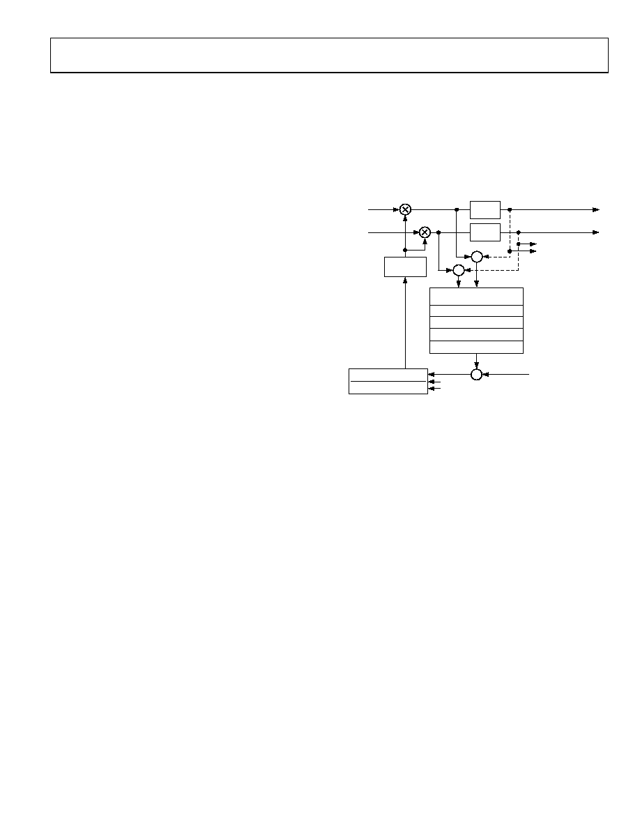
Two data paths to the AGC loop are provided: one befor
clipping circuitry and one after the clipping circuitry, as shown
in Figure 42. For desired signal level mode, only the I/Q path
before the clipping is used. For desired clipping level mode
difference of the I/Q signals before and after the clipping
circuitry is use
CLIP
I
23 BITS
CLIP
Q
MEAN SQUARE (I+jQ)
AVERAGE 1-16384 SAMPLES
DECIMATE 1-4096 SAMPLES
SQUARE ROOT
USED ONLY FOR
DESIRED
CLIPPING LEVEL
MODE
GAIN
I
Q
MULTIPLIER
–
2x
POWER OF 2
K
× z–1
1 – (1 + P)
ERROR
× z–1 + P × z–2
'K' GAIN
'P' POLE
+
–
'R' DESIRED
PROGRAMMABLE
BIT WIDTH
LOG2(X)
03198-
DESIRED SIGNAL LEVEL MODE
d
GC loop has average and decimate blocks that operate on
and the decimate block can be
programmed to update the AGC once every 1 to 4096 samples.
The limitations on the averaging operation are that the number
of averaged power samples must be an integer multiple of the
ower of 1 to 16384 output samples.
The choice of updating the AGC once every 1 to 4096 samples
and operating on average power facilitates the implementation
0-
038
Figure 42. Block Diagram of the AGC
In this mode of operation, the AGC strives to maintain the
output signal at a programmable set level. This mode of
operation is selected by writing AGC control word (0x0A:4, an
0x12:4) to logic zero. First, the loop finds the square (or power)
of the incoming complex data signal by squaring I and Q and
adding them. This operation is implemented in exponential
domain using 2x (power of 2).
The A
power samples before the square root operation, as shown in
Figure 42. The average block can be programmed to average 1
to 16384 power samples,
decimation value, and the only allowable multiple values are 1,
2, 3, or 4.
The averaging and decimation effectively mean that the AGC
can operate over averaged p
of a loop filter with slow time constants, where the AGC error
converges slowly and makes infrequent gain adjustments. It
would also be useful where the user wants to keep the gain
相關(guān)PDF資料 |
PDF描述 |
|---|---|
| AD7575JP-REEL | 1-CH 8-BIT SUCCESSIVE APPROXIMATION ADC, PARALLEL ACCESS, PQCC20 |
| AD7575KP-REEL | 1-CH 8-BIT SUCCESSIVE APPROXIMATION ADC, PARALLEL ACCESS, PQCC20 |
| AD7741YR-REEL7 | VOLTAGE-FREQUENCY CONVERTER, 6.144 MHz, PDSO8 |
| AD8402AR1-REEL | DUAL 1K DIGITAL POTENTIOMETER, 3-WIRE SERIAL CONTROL INTERFACE, 256 POSITIONS, PDSO14 |
| AD8402ARU100-REEL | DUAL 100K DIGITAL POTENTIOMETER, 3-WIRE SERIAL CONTROL INTERFACE, 256 POSITIONS, PDSO14 |
相關(guān)代理商/技術(shù)參數(shù) |
參數(shù)描述 |
|---|---|
| AD6653 | 制造商:AD 制造商全稱:Analog Devices 功能描述:IF Diversity Receiver |
| AD6653-125EBZ | 制造商:Analog Devices 功能描述:Evaluation Board For AD6653 制造商:Analog Devices 功能描述:EVAL BD FOR AD6653 - Bulk 制造商:Analog Devices 功能描述:KIT EVALUATION BOARD AD6653 |
| AD6653-150EBZ | 制造商:Analog Devices 功能描述:EVAL BD FOR AD6653 - Bulk |
| AD6653BCPZ-125 | 制造商:Analog Devices 功能描述:IF DIVERSITY RCVR 64LFCSP EP - Trays 制造商:Rochester Electronics LLC 功能描述: 制造商:Analog Devices 功能描述:IC RECEIVER IF DIVERSITY LFCSP64 |
| AD6653BCPZ-150 | 制造商:Analog Devices 功能描述:IF DIVERSITY RCVR 64LFCSP EP - Trays 制造商:Analog Devices 功能描述:IC RECEIVER IF DIVERSITY LFCSP64 制造商:Analog Devices 功能描述:IC, RECEIVER, IF DIVERSITY, LFCSP64 |
發(fā)布緊急采購,3分鐘左右您將得到回復(fù)。