- 您現(xiàn)在的位置:買賣IC網(wǎng) > PDF目錄298813 > AD6652XBC (ANALOG DEVICES INC) SPECIALTY TELECOM CIRCUIT, PBGA256 PDF資料下載
參數(shù)資料
| 型號: | AD6652XBC |
| 廠商: | ANALOG DEVICES INC |
| 元件分類: | 通信及網(wǎng)絡(luò) |
| 英文描述: | SPECIALTY TELECOM CIRCUIT, PBGA256 |
| 封裝: | 17 X 17 MM, MINI, BGA-256 |
| 文件頁數(shù): | 29/76頁 |
| 文件大小: | 1802K |
| 代理商: | AD6652XBC |
第1頁第2頁第3頁第4頁第5頁第6頁第7頁第8頁第9頁第10頁第11頁第12頁第13頁第14頁第15頁第16頁第17頁第18頁第19頁第20頁第21頁第22頁第23頁第24頁第25頁第26頁第27頁第28頁當(dāng)前第29頁第30頁第31頁第32頁第33頁第34頁第35頁第36頁第37頁第38頁第39頁第40頁第41頁第42頁第43頁第44頁第45頁第46頁第47頁第48頁第49頁第50頁第51頁第52頁第53頁第54頁第55頁第56頁第57頁第58頁第59頁第60頁第61頁第62頁第63頁第64頁第65頁第66頁第67頁第68頁第69頁第70頁第71頁第72頁第73頁第74頁第75頁第76頁

Preliminary Technical Data
AD6652
Rev. PrC | Page 35 of 76
ion,
FIFTH-ORDER CIC FILTER
The fourth signal processing stage, CIC5, implements a sharper
fixed-coefficient, decimating filter than rCIC2. The input rate to
this filter is ∫SAMP2. The maximum input rate is given by the
following equation. NCH equals two for diversity channel real
input mode; otherwise, NCH equals one. To satisfy this equat
increase MrCIC2 or reduce NCH.
CH
CLK
SAMP
N
∫
≤
∫
2
The decimation ratio, MCIC5, may e programmed from 2 to 32
(all integer v
iven
y the following equations. Use these equations to calculate the
gain and pass-band droop of CIC5. Both parameters may be
b
alues). The frequency response of the filter is g
b
compensated for in the RCF stage.
5
1
5
1
2
1
)
(
5
×
=
+
z
H
CIC
M
S
5
2
5
sin
2
1
)
(
5
∫
π
∫
×
=
∫
+
SAMP
S
H
CIC
The scale factor, S
5
∫
×
CIC
ull
sin
π
M
CIC5
, is a programmable unsigned integer
between 0 and 20. It serves to control the attenuation of the data
into the CIC5 stage in 6 dB increments. For the best dynamic
range, set SCIC5 to the least attenuation without creating an
overflow condition. This can be safely accomplished using the
following equation, where OLrCIC2 is the largest fraction of f
scale possible at the input to this filter stage. This value is output
from the rCIC2 stage, then pipelined into the CIC5.
(
)
(
) 5
log
2
5
2
5 =
C
CIC
M
ceil
S
×
rCIC
IC
OL
()
2
5
2
rCIC
S
CIC
OL
M
OL
CIC
×
=
+
The output rate of this stage is given by the following equation:
5
2
5
CIC
SAMP
M
∫
=
∫
CIC5 REJECTION
Table 15 lists the amount of bandwidth in percentage of the
input rate that can be protected with various decimation rates
and alias rejection specifications. The maximum input rate i
the CIC5 is 65 MHz when the rCIC2 decimates by 1. As in the
previous rCIC2 table (Table 14), these are the single-sideband
bandwidth characteristics of the CIC5.
The CIC5 stage can protect a much wider band to any given
rejection than rCIC2.
nto
e
Given the desired filter characteristics, Table 15 can help in th
calculation of an upper bound on decimation, MCIC5.
Table 15. SSB CIC5 Alias Rejection Table (fSAMP2 = 1)
MCIC5
50 dB
60 dB
70 dB
80 dB
90 dB
100 dB
2
10.277
8.078
6.393
5.066
4.008
3.183
3
7.924
6.367
5.11
4.107
3.297
2.642
4
6.213
5.022
4.057
3.271
2.636
2.121
5
5.068
4.107
3.326
2.687
2.17
1.748
6
4.267
3.463
2.808
2.27
1.836
1.48
7
3.68
2.989
2.425
1.962
1.588
1.281
8
3.233
2.627
2.133
1.726
1.397
1.128
9
2.881
2.342
1.902
1.54
1.247
1.007
10
2.598
2.113
1.716
1.39
1.125
0.909
11
2.365
1.924
1.563
1.266
1.025
0.828
12
2.17
1.765
1.435
1.162
0.941
0.76
13
2.005
1.631
1.326
1.074
0.87
0.703
14
1.863
1.516
1.232
0.998
0.809
0.653
15
1.74
1.416
1.151
0.932
0.755
0.61
16
1.632
1.328
1.079
0.874
0.708
0.572
17
1.536
1.25
1.016
0.823
0.667
0.539
18
1.451
1.181
0.96
0.778
0.63
0.509
19
1.375
1.119
0.91
0.737
0.597
0.483
20
1.307
1.064
568
0.865
0.701
0.
0.459
21
1.245
1.013
0.667
0.541
0.824
0.437
22
1.188
0.967
0.637
0.516
0.417
0.786
23
1.137
0.925
0.61
0.494
0.752
0.399
24
1.09
0.887
0.721
0.584
0.474
0.383
25
1.046
0.852
0.692
0.561
0.455
0.367
26
1.006
0.819
0.666
0.54
0.437
0.353
27
0.969
0.789
0.641
0.52
0.421
0.34
28
0.934
0.761
0.618
0.501
0.406
0.328
29
0.902
0.734
0.597
0.484
0.392
0.317
30
0.872
0.71
0.577
0.468
0.379
0.306
31
0.844
0.687
0.559
0.453
0.367
0.297
32
0.818
0.666
0.541
0.439
0.355
0.287
–150
–130
–2
–1
0
1
2
–110
–90
–30
–10
+10
–70
–50
dB
MULTIPLES OF CIC5 OUTPUT RATE
03198-0-035
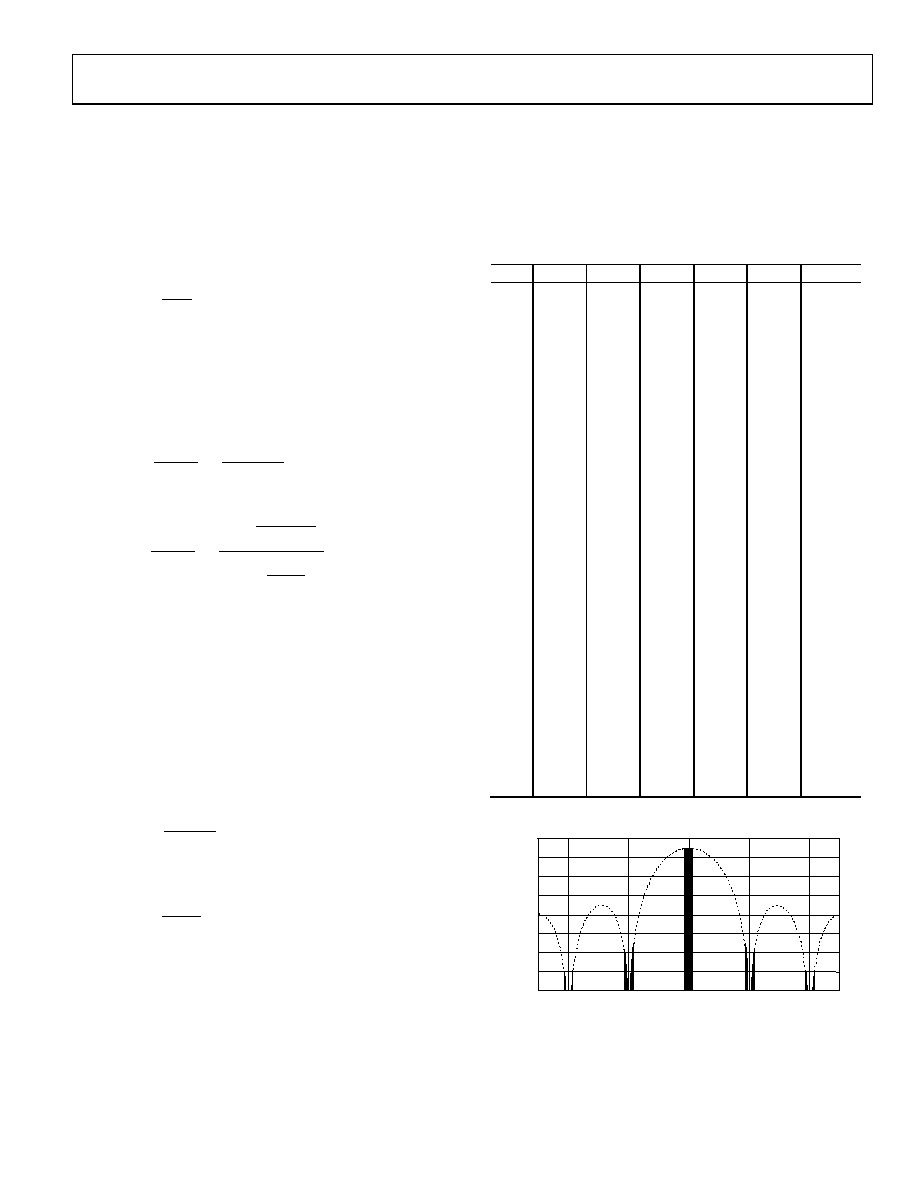
Figure 39. Double Side-Band Graph Showing CIC5 Filter Response
and Alias Rejection of 100 dB
相關(guān)PDF資料 |
PDF描述 |
|---|---|
| AD7575JP-REEL | 1-CH 8-BIT SUCCESSIVE APPROXIMATION ADC, PARALLEL ACCESS, PQCC20 |
| AD7575KP-REEL | 1-CH 8-BIT SUCCESSIVE APPROXIMATION ADC, PARALLEL ACCESS, PQCC20 |
| AD7741YR-REEL7 | VOLTAGE-FREQUENCY CONVERTER, 6.144 MHz, PDSO8 |
| AD8402AR1-REEL | DUAL 1K DIGITAL POTENTIOMETER, 3-WIRE SERIAL CONTROL INTERFACE, 256 POSITIONS, PDSO14 |
| AD8402ARU100-REEL | DUAL 100K DIGITAL POTENTIOMETER, 3-WIRE SERIAL CONTROL INTERFACE, 256 POSITIONS, PDSO14 |
相關(guān)代理商/技術(shù)參數(shù) |
參數(shù)描述 |
|---|---|
| AD6653 | 制造商:AD 制造商全稱:Analog Devices 功能描述:IF Diversity Receiver |
| AD6653-125EBZ | 制造商:Analog Devices 功能描述:Evaluation Board For AD6653 制造商:Analog Devices 功能描述:EVAL BD FOR AD6653 - Bulk 制造商:Analog Devices 功能描述:KIT EVALUATION BOARD AD6653 |
| AD6653-150EBZ | 制造商:Analog Devices 功能描述:EVAL BD FOR AD6653 - Bulk |
| AD6653BCPZ-125 | 制造商:Analog Devices 功能描述:IF DIVERSITY RCVR 64LFCSP EP - Trays 制造商:Rochester Electronics LLC 功能描述: 制造商:Analog Devices 功能描述:IC RECEIVER IF DIVERSITY LFCSP64 |
| AD6653BCPZ-150 | 制造商:Analog Devices 功能描述:IF DIVERSITY RCVR 64LFCSP EP - Trays 制造商:Analog Devices 功能描述:IC RECEIVER IF DIVERSITY LFCSP64 制造商:Analog Devices 功能描述:IC, RECEIVER, IF DIVERSITY, LFCSP64 |
發(fā)布緊急采購,3分鐘左右您將得到回復(fù)。