- 您現(xiàn)在的位置:買賣IC網(wǎng) > PDF目錄383185 > IT8673F (Electronic Theatre Controls, Inc.) GT 35C 35#12 SKT PLUG PDF資料下載
參數(shù)資料
| 型號: | IT8673F |
| 廠商: | Electronic Theatre Controls, Inc. |
| 英文描述: | GT 35C 35#12 SKT PLUG |
| 中文描述: | 先進(jìn)的輸入/輸出(高級I / O)的初步規(guī)范V0.5 |
| 文件頁數(shù): | 54/128頁 |
| 文件大?。?/td> | 780K |
| 代理商: | IT8673F |
第1頁第2頁第3頁第4頁第5頁第6頁第7頁第8頁第9頁第10頁第11頁第12頁第13頁第14頁第15頁第16頁第17頁第18頁第19頁第20頁第21頁第22頁第23頁第24頁第25頁第26頁第27頁第28頁第29頁第30頁第31頁第32頁第33頁第34頁第35頁第36頁第37頁第38頁第39頁第40頁第41頁第42頁第43頁第44頁第45頁第46頁第47頁第48頁第49頁第50頁第51頁第52頁第53頁當(dāng)前第54頁第55頁第56頁第57頁第58頁第59頁第60頁第61頁第62頁第63頁第64頁第65頁第66頁第67頁第68頁第69頁第70頁第71頁第72頁第73頁第74頁第75頁第76頁第77頁第78頁第79頁第80頁第81頁第82頁第83頁第84頁第85頁第86頁第87頁第88頁第89頁第90頁第91頁第92頁第93頁第94頁第95頁第96頁第97頁第98頁第99頁第100頁第101頁第102頁第103頁第104頁第105頁第106頁第107頁第108頁第109頁第110頁第111頁第112頁第113頁第114頁第115頁第116頁第117頁第118頁第119頁第120頁第121頁第122頁第123頁第124頁第125頁第126頁第127頁第128頁
IT8673F
4
44
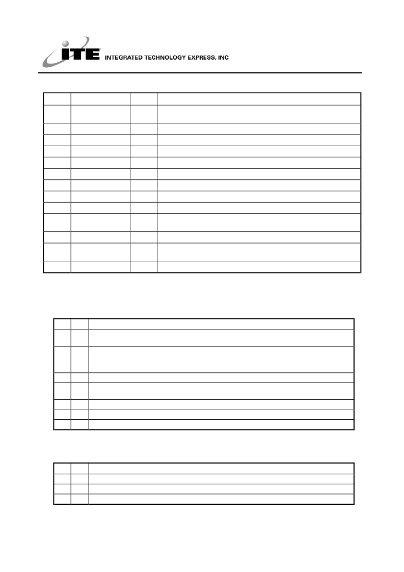
Table 11-2. FAN Controller Registers
Index
Register
Default
Description
28h-2Ah Reading
-
FAN Tachometer 1-3 Reading Register; the counts number of the internal
clock per resolution
3Bh-3Dh FAN_TAC1-3 Limit
-
FAN Tachometer 1-3 Count Limit Register
40h
Configuration
08h
41h
Interrupt Status 1
00h
Auto increment to the index of Interrupt status 2
42h
Interrupt Status 2
00h
43h
SMI# Mask 1
00h
Auto increment to the index of SMI# Mask 2
44h
SMI# Mask 2
00h
45h
Interrupt Mask 1
00h
Auto increment to the index of Interrupt Mask 2
46h
Interrupt Mask 2
0Xh
47h
FAN Tachometer
Divisor
5Xh
The divisor values of the FAN Tachometer.
51h
FAN control
00h
FAN control registers
52h
FAN Set X PWM
Control
00h
FAN PWM Control Register
58h
Vendor ID
90h
ITE Vendor ID.
Read Only
Register
Note: X indicates 1 or 2 or 3.
11.3.2.2
11.3.2.2.1 Configuration Register (Index=40h, Default=08h)
Bit R/W
Register Description
Description
7
R/W Initialization. A “1” restores all registers to their individual default values, except the Serial Bus
Address register. This bit clears itself when the default value is “0”.
6
R/W ON/OFF control of FAN_CTL1. This bit is used to control FAN_CTL1 when FAN_CTL1 mode (Bit 0 of
the register Index=51h) is set to ON_OFF mode.
0: OFF. 1: ON.
5-4
Reserved
3
R/W INT_Clear. A ”1” disables the SMI# and IRQ outputs with the contents of interrupt status bits remain
unchanged.
2
R/W IRQ enables the IRQ Interrupt output.
1
R/W SMI# Enable. A “1” enables the SMI# Interrupt output.
0
R/W Reserved
11.3.2.2.2 Interrupt Status Register 1 (Index=41h, Default=00h)
Reading this register will clear itself following a read access.
Bit R/W
Description
7
R
A “1” indicates the FAN Count 2 limit has been reached.
6
R
A “1” indicates the FAN Count 1 limit has been reached.
5-0
-
Reserved
相關(guān)PDF資料 |
PDF描述 |
|---|---|
| IT8687R | GT 35C 35#12 SKT PLUG |
| ITC1000 | GT 85C 85#16 SKT PLUG |
| ITF86130SK8T | N-Channel, Logic Level, Power MOSFET(N溝道邏輯電平功率MOS場效應(yīng)管) |
| ITF86182SK8T | 11A, 30V, 0.0115 Ohm, P-Channel, Logic Level, Power MOSFET |
| ITF87012SVT | 6A, 20V, 0.035 Ohm, N-Channel,2.5V Specified Power MOSFET(6A, 20V, 0.035Ω N溝道2.5V專用功率MOS場效應(yīng)管) |
相關(guān)代理商/技術(shù)參數(shù) |
參數(shù)描述 |
|---|---|
| IT8687R | 制造商:ITE 功能描述: |
| IT86B | 制造商:未知廠家 制造商全稱:未知廠家 功能描述:TRIAC|600V V(DRM)|8A I(T)RMS|TO-220 |
| IT86C | 制造商:未知廠家 制造商全稱:未知廠家 功能描述:TRIAC|600V V(DRM)|8A I(T)RMS|TO-220 |
| IT86F | 制造商:未知廠家 制造商全稱:未知廠家 功能描述:TRIAC|600V V(DRM)|8A I(T)RMS|TO-220 |
| IT86G | 制造商:未知廠家 制造商全稱:未知廠家 功能描述:TRIAC|600V V(DRM)|8A I(T)RMS|TO-220 |
發(fā)布緊急采購,3分鐘左右您將得到回復(fù)。