- 您現(xiàn)在的位置:買賣IC網(wǎng) > PDF目錄383185 > IT8673F (Electronic Theatre Controls, Inc.) GT 35C 35#12 SKT PLUG PDF資料下載
參數(shù)資料
| 型號: | IT8673F |
| 廠商: | Electronic Theatre Controls, Inc. |
| 英文描述: | GT 35C 35#12 SKT PLUG |
| 中文描述: | 先進的輸入/輸出(高級I / O)的初步規(guī)范V0.5 |
| 文件頁數(shù): | 111/128頁 |
| 文件大?。?/td> | 780K |
| 代理商: | IT8673F |
第1頁第2頁第3頁第4頁第5頁第6頁第7頁第8頁第9頁第10頁第11頁第12頁第13頁第14頁第15頁第16頁第17頁第18頁第19頁第20頁第21頁第22頁第23頁第24頁第25頁第26頁第27頁第28頁第29頁第30頁第31頁第32頁第33頁第34頁第35頁第36頁第37頁第38頁第39頁第40頁第41頁第42頁第43頁第44頁第45頁第46頁第47頁第48頁第49頁第50頁第51頁第52頁第53頁第54頁第55頁第56頁第57頁第58頁第59頁第60頁第61頁第62頁第63頁第64頁第65頁第66頁第67頁第68頁第69頁第70頁第71頁第72頁第73頁第74頁第75頁第76頁第77頁第78頁第79頁第80頁第81頁第82頁第83頁第84頁第85頁第86頁第87頁第88頁第89頁第90頁第91頁第92頁第93頁第94頁第95頁第96頁第97頁第98頁第99頁第100頁第101頁第102頁第103頁第104頁第105頁第106頁第107頁第108頁第109頁第110頁當前第111頁第112頁第113頁第114頁第115頁第116頁第117頁第118頁第119頁第120頁第121頁第122頁第123頁第124頁第125頁第126頁第127頁第128頁
IT8673F
101
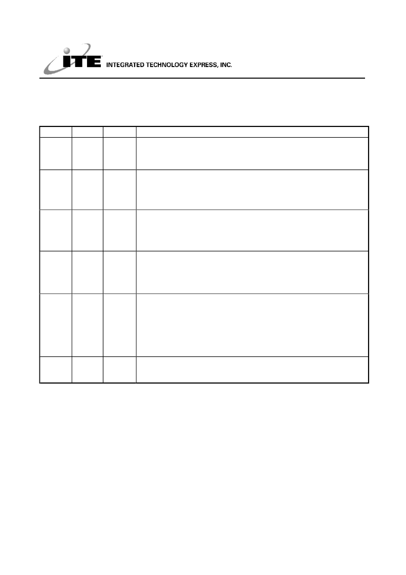
11.8.6.3 CIR Receiver Control Register (RCR)
The RCR, an 8-bit
read/write
register, is used to control the CIR Receiver.
Address: Base address + 2h
Bit
7
R/W
Default
0b
Description
R/W
Receiver Data Without Sync. (RDWOS)
This bit is used to control the sync. logic for Receiving data.
Set this bit to “1” to obtain the receiving data without sync. logic.
Set this bit to “0” to obtain the receiving data in sync. logic.
High-Speed Carrier Frequency Select (HCFS)
This bit is used to select Carrier Frequency between high-speed and
low-speed.
0
30-58 kHz (Default)
1
400-500 kHz
Receiver Enable (RXEN)
This bit is used to enable Receiver function. Enable Receiver and the RXACT
will be active if the selected carrier frequency is received.
Set this bit to “1” to enable the Receiver function.
Set this bit to “0” to disable the Receiver function.
Receiver Demodulation Enable (RXEND)
This bit is used to control the Receiver Demodulation logic. If the Receiver
device can not demodulate the correct carrier, set this bit to “1”.
Set this bit to “1” to enable Receiver Demodulation logic.
Set this bit to “0” to disable Receiver Demodulation logic.
Receiver Active (RXACT)
This bit is used to control the Receiver operation.
This bit is set to “0” when the Receiver is inactive.
This bit will be set to “1” when the Receiver detects a pulse (RXEND=0) or
pulse-train (RXEND=1) with correct carrier frequency. The Receiver then
starts to sample the input data when Receiver Active is set. Write a “1” to this
bit to clear the Receiver Active condition and make the Receiver enter the
inactive mode.
Receiver Demodulation Carrier Range (RXDCR[2:0])
These three bits are used to set the tolerance of the Receiver Demodulation
carrier frequency. See Table 11-48 and Table 11-49.
6
R/W
0b
5
R/W
0b
4
R/W
0b
3
R/W
0b
2-0
R/W
001b
相關PDF資料 |
PDF描述 |
|---|---|
| IT8687R | GT 35C 35#12 SKT PLUG |
| ITC1000 | GT 85C 85#16 SKT PLUG |
| ITF86130SK8T | N-Channel, Logic Level, Power MOSFET(N溝道邏輯電平功率MOS場效應管) |
| ITF86182SK8T | 11A, 30V, 0.0115 Ohm, P-Channel, Logic Level, Power MOSFET |
| ITF87012SVT | 6A, 20V, 0.035 Ohm, N-Channel,2.5V Specified Power MOSFET(6A, 20V, 0.035Ω N溝道2.5V專用功率MOS場效應管) |
相關代理商/技術參數(shù) |
參數(shù)描述 |
|---|---|
| IT8687R | 制造商:ITE 功能描述: |
| IT86B | 制造商:未知廠家 制造商全稱:未知廠家 功能描述:TRIAC|600V V(DRM)|8A I(T)RMS|TO-220 |
| IT86C | 制造商:未知廠家 制造商全稱:未知廠家 功能描述:TRIAC|600V V(DRM)|8A I(T)RMS|TO-220 |
| IT86F | 制造商:未知廠家 制造商全稱:未知廠家 功能描述:TRIAC|600V V(DRM)|8A I(T)RMS|TO-220 |
| IT86G | 制造商:未知廠家 制造商全稱:未知廠家 功能描述:TRIAC|600V V(DRM)|8A I(T)RMS|TO-220 |
發(fā)布緊急采購,3分鐘左右您將得到回復。