- 您現(xiàn)在的位置:買賣IC網(wǎng) > PDF目錄369945 > P8XC591 (NXP Semiconductors N.V.) HiRel FPGA, Low-Power 1.0?? CMOS Technology PDF資料下載
參數(shù)資料
| 型號: | P8XC591 |
| 廠商: | NXP Semiconductors N.V. |
| 英文描述: | HiRel FPGA, Low-Power 1.0?? CMOS Technology |
| 中文描述: | 單芯片8 - CAN控制器位微控制器 |
| 文件頁數(shù): | 46/160頁 |
| 文件大?。?/td> | 601K |
| 代理商: | P8XC591 |
第1頁第2頁第3頁第4頁第5頁第6頁第7頁第8頁第9頁第10頁第11頁第12頁第13頁第14頁第15頁第16頁第17頁第18頁第19頁第20頁第21頁第22頁第23頁第24頁第25頁第26頁第27頁第28頁第29頁第30頁第31頁第32頁第33頁第34頁第35頁第36頁第37頁第38頁第39頁第40頁第41頁第42頁第43頁第44頁第45頁當(dāng)前第46頁第47頁第48頁第49頁第50頁第51頁第52頁第53頁第54頁第55頁第56頁第57頁第58頁第59頁第60頁第61頁第62頁第63頁第64頁第65頁第66頁第67頁第68頁第69頁第70頁第71頁第72頁第73頁第74頁第75頁第76頁第77頁第78頁第79頁第80頁第81頁第82頁第83頁第84頁第85頁第86頁第87頁第88頁第89頁第90頁第91頁第92頁第93頁第94頁第95頁第96頁第97頁第98頁第99頁第100頁第101頁第102頁第103頁第104頁第105頁第106頁第107頁第108頁第109頁第110頁第111頁第112頁第113頁第114頁第115頁第116頁第117頁第118頁第119頁第120頁第121頁第122頁第123頁第124頁第125頁第126頁第127頁第128頁第129頁第130頁第131頁第132頁第133頁第134頁第135頁第136頁第137頁第138頁第139頁第140頁第141頁第142頁第143頁第144頁第145頁第146頁第147頁第148頁第149頁第150頁第151頁第152頁第153頁第154頁第155頁第156頁第157頁第158頁第159頁第160頁

2000 Jul 26
46
Philips Semiconductors
Preliminary Specification
Single-chip 8-bit microcontroller with CAN controller
P8xC591
12.5.16 TX E
RROR
C
OUNTER
R
EGISTER
(TXERR)
The TX Error Counter Register reflects the current value of
the Transmit Error Counter. In Operating Mode this
register appears to the CPU as a read only memory. A
writeaccesstothisregisterispossibleonlyinResetMode.
After hardware reset this register is initialised to “0”. If a
bus-off event occurs, the TX Error Counter is initialised to
127 to count the minimum protocol-defined time (128
occurrences of the Bus-Free signal). Reading the TX Error
Counter during this time gives information about the status
of the Bus-Off recovery.
If Bus Off is active, a write access to TXERR in the range
of 0 to 254 clears the Bus Off Flag and the controller will
wait for one occurrence of 11 consecutive recessive bits
(bus free) after clearing of Reset Mode.
Writing 255 to TXERR allows to initiate a CPU-driven Bus
Off event. Note, that a CPU-forced content change of the
TX Error Counter is possible only, if the Reset Mode was
entered previously. An Error or Bus Status change (Status
Register), an Error Warning or an Error Passive Interrupt
forced by the new register content will not occur, until the
Reset Mode is cancelled again. After leaving the Reset
Mode, the new TX Counter content is interpreted and the
Bus Off event is performed in the same way, as if it was
forced by a bus error event. That means, that the Reset
Mode is entered again, the TX Error Counter is initialised
to 127, the RX Counter is cleared and all concerned Status
and Interrupt Register Bits are set.
Clearing of Reset Mode now will perform the protocol
defined Bus Off recovery sequence (waiting for 128
occurrences of the Bus-Free signal).
If the Reset Mode is entered again before the end of Bus
Off recovery (TXERR > 0), Bus Off keeps active and
TXERR is frozen.
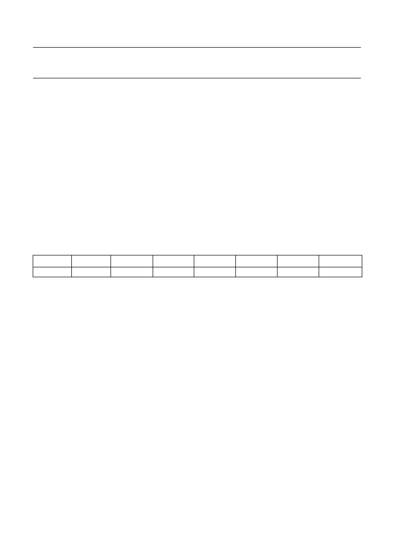
Table 30
TX Error Counter Register (TXERR) (CAN address 15)
7
6
5
4
3
2
1
0
TXERR.7
TXERR.6
TXERR.5
TXERR.4
TXERR.3
TXERR.2
TXERR.1
TXERR.0
12.5.17 A
CCEPTANCE
F
ILTER
With the help of the Acceptance Filter the CAN controller
is able to allow passing of received messages to the
RXFIFO only when the identifier bits and the Frame Type
of the received message are equal to the predefined ones
within the Acceptance Filter Registers. If at least one filter
matches, the message is copied to the receive FIFO.
The Acceptance Filter is defined by the Acceptance Code
Registers (ACRn) and the Acceptance Mask Registers
(AMRn). Within the Acceptance Code Registers the bit
patterns of messages to be received are defined. The
corresponding Acceptance Mask Registers allow defining
certain bit positions to be “don‘t care”.
The PeliCAN is designed to support four of so called
Acceptance Filter Banks. Each bank has the functionality
known from the SJA1000 with the extension, that a filter
change is possible “on the fly”. Additionally the used
Frame Format of each filter bank is programmable now.
相關(guān)PDF資料 |
PDF描述 |
|---|---|
| P90CE201 | 16-bit microcontroller |
| P90CE201AEB | 16-bit microcontroller |
| P9217 | PbS photoconductive detector |
| P930 | CdS photoconductive cell |
| PA025XSB | This technical specification applies to 2.5inch color TFT-LCD panel. |
相關(guān)代理商/技術(shù)參數(shù) |
參數(shù)描述 |
|---|---|
| P8XC592 | 制造商:PHILIPS 制造商全稱:NXP Semiconductors 功能描述:8-bit microcontroller with on-chip CAN |
| P8XCE598 | 制造商:PHILIPS 制造商全稱:NXP Semiconductors 功能描述:8-bit microcontroller with on-chip CAN |
| P8XCL580HFH | 制造商:PHILIPS 制造商全稱:NXP Semiconductors 功能描述:Low voltage 8-bit microcontrollers with UART, I2C-bus and ADC |
| P8XCL580HFT | 制造商:PHILIPS 制造商全稱:NXP Semiconductors 功能描述:Low voltage 8-bit microcontrollers with UART, I2C-bus and ADC |
| P8Z77 DELUXE | 制造商:Asus 功能描述:P8Z77-V Deluxe ATX Motherboard |
發(fā)布緊急采購,3分鐘左右您將得到回復(fù)。