- 您現(xiàn)在的位置:買賣IC網 > PDF目錄366552 > AM8530 (Advanced Micro Devices, Inc.) Serial Communications Controller PDF資料下載
參數(shù)資料
| 型號: | AM8530 |
| 廠商: | Advanced Micro Devices, Inc. |
| 英文描述: | Serial Communications Controller |
| 中文描述: | 串行通信控制器 |
| 文件頁數(shù): | 160/194頁 |
| 文件大?。?/td> | 797K |
| 代理商: | AM8530 |
第1頁第2頁第3頁第4頁第5頁第6頁第7頁第8頁第9頁第10頁第11頁第12頁第13頁第14頁第15頁第16頁第17頁第18頁第19頁第20頁第21頁第22頁第23頁第24頁第25頁第26頁第27頁第28頁第29頁第30頁第31頁第32頁第33頁第34頁第35頁第36頁第37頁第38頁第39頁第40頁第41頁第42頁第43頁第44頁第45頁第46頁第47頁第48頁第49頁第50頁第51頁第52頁第53頁第54頁第55頁第56頁第57頁第58頁第59頁第60頁第61頁第62頁第63頁第64頁第65頁第66頁第67頁第68頁第69頁第70頁第71頁第72頁第73頁第74頁第75頁第76頁第77頁第78頁第79頁第80頁第81頁第82頁第83頁第84頁第85頁第86頁第87頁第88頁第89頁第90頁第91頁第92頁第93頁第94頁第95頁第96頁第97頁第98頁第99頁第100頁第101頁第102頁第103頁第104頁第105頁第106頁第107頁第108頁第109頁第110頁第111頁第112頁第113頁第114頁第115頁第116頁第117頁第118頁第119頁第120頁第121頁第122頁第123頁第124頁第125頁第126頁第127頁第128頁第129頁第130頁第131頁第132頁第133頁第134頁第135頁第136頁第137頁第138頁第139頁第140頁第141頁第142頁第143頁第144頁第145頁第146頁第147頁第148頁第149頁第150頁第151頁第152頁第153頁第154頁第155頁第156頁第157頁第158頁第159頁當前第160頁第161頁第162頁第163頁第164頁第165頁第166頁第167頁第168頁第169頁第170頁第171頁第172頁第173頁第174頁第175頁第176頁第177頁第178頁第179頁第180頁第181頁第182頁第183頁第184頁第185頁第186頁第187頁第188頁第189頁第190頁第191頁第192頁第193頁第194頁
SCC Application Notes
AMD
7–11
7.3
INT ERRUPT WIT HOUT INT ACK AS Y NCHRONOUS
MODE
Introduc tion
This section describes the use of the SCC for interrupt-driven Asynchronous mode. As
with the example in the previous chapter, the SCC is set with 8 bits per character, 2 stop
bits, at 9600 baud rate. An external 2.4576 MHz, crystal oscillator is used for baud-rate
generation. Interrupt acknowledge is not generated because of the extra hardware re-
quired to produce this signal. In this chapter, the SCC is also programmed for local loop-
back so that no external loop between the transmit and the receive data lines is needed
for on-board diagnostics. This feature allows the user to test-program the part without
additional hardware to simulate an actual transmit and receive environment.
7.3.1
7.3.2
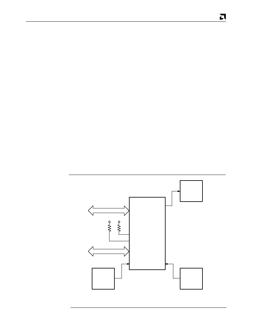
Figure 7–4 shows the SCC to CPU interface required for this application. The 8-bit data
bus and control lines all come from the user’s CPU. The control lines are
RD
,
WR
, A/
B
,
D/
C
and
CE
. The
INT
signal goes to an interrupt controller which must produce the inter-
rupt vector to the CPU. The PCLK comes from the system clock, or an external crystal
oscillator, up to the maximum rate of the SCC (e.g., 6 MHz for the Am8530A). The IEI
and the
INTACK
pins should be pulled up. The baud-rate generator clock is connected to
the
RTxC
pin.
S CC Interfac e
7.3.3
The initialization of the SCC for interrupt-driven asynchronous communication is divided
into three parts as shown in Table 7–6. Part one programs the operating modes of the
SCC, part two and three enable them. Care must be taken when writing the code to meet
the SCC’s Cycle and Reset Recovery times. The Cycle Recovery time applies to the pe-
riod between any Read or Write cycles to the SCC, and is 6 PCLK cycles. The Reset Re-
covery time applies to a hardware reset caused either by hardware or software; this
recovery time extends the Cycle Recovery time to 11 PCLK cycles.
S CC Initialization
Data
8
Control
5
System
V
CC
V
CC
XTAL
OSC
2.4576 MHz
OSC
PCLK
RTxC
INTACK
IEI
D0 – D7
SCC
Pin 12 For Channel A
Pin 28 For Channel B
Interrupt
Controller
INT
Figure 7–4. SCC Interface
相關PDF資料 |
PDF描述 |
|---|---|
| AM8530H | Serial Communications Controller |
| AM85C30-10PC | Enhanced Serial Communications Controller |
| Am85C30 | Serial Communications Controller |
| AM85C30 | Enhanced Serial Communications Controller |
| AM85C30-8PC | Enhanced Serial Communications Controller |
相關代理商/技術參數(shù) |
參數(shù)描述 |
|---|---|
| AM8530ADC | 制造商:未知廠家 制造商全稱:未知廠家 功能描述:Communications Controller |
| AM8530ADCB | 制造商:未知廠家 制造商全稱:未知廠家 功能描述:Communications Controller |
| AM8530AJC | 制造商:未知廠家 制造商全稱:未知廠家 功能描述:Communications Controller |
| AM8530APC | 制造商:未知廠家 制造商全稱:未知廠家 功能描述:Communications Controller |
| AM8530DC | 制造商:未知廠家 制造商全稱:未知廠家 功能描述:Communications Controller |
發(fā)布緊急采購,3分鐘左右您將得到回復。