- 您現(xiàn)在的位置:買賣IC網(wǎng) > PDF目錄69029 > MC916X1CTH16B1 (FREESCALE SEMICONDUCTOR INC) 16-BIT, FLASH, 16.78 MHz, MICROCONTROLLER, PQFP120 PDF資料下載
參數(shù)資料
| 型號(hào): | MC916X1CTH16B1 |
| 廠商: | FREESCALE SEMICONDUCTOR INC |
| 元件分類: | 微控制器/微處理器 |
| 英文描述: | 16-BIT, FLASH, 16.78 MHz, MICROCONTROLLER, PQFP120 |
| 封裝: | QFP-120 |
| 文件頁(yè)數(shù): | 167/172頁(yè) |
| 文件大?。?/td> | 1200K |
| 代理商: | MC916X1CTH16B1 |
第1頁(yè)第2頁(yè)第3頁(yè)第4頁(yè)第5頁(yè)第6頁(yè)第7頁(yè)第8頁(yè)第9頁(yè)第10頁(yè)第11頁(yè)第12頁(yè)第13頁(yè)第14頁(yè)第15頁(yè)第16頁(yè)第17頁(yè)第18頁(yè)第19頁(yè)第20頁(yè)第21頁(yè)第22頁(yè)第23頁(yè)第24頁(yè)第25頁(yè)第26頁(yè)第27頁(yè)第28頁(yè)第29頁(yè)第30頁(yè)第31頁(yè)第32頁(yè)第33頁(yè)第34頁(yè)第35頁(yè)第36頁(yè)第37頁(yè)第38頁(yè)第39頁(yè)第40頁(yè)第41頁(yè)第42頁(yè)第43頁(yè)第44頁(yè)第45頁(yè)第46頁(yè)第47頁(yè)第48頁(yè)第49頁(yè)第50頁(yè)第51頁(yè)第52頁(yè)第53頁(yè)第54頁(yè)第55頁(yè)第56頁(yè)第57頁(yè)第58頁(yè)第59頁(yè)第60頁(yè)第61頁(yè)第62頁(yè)第63頁(yè)第64頁(yè)第65頁(yè)第66頁(yè)第67頁(yè)第68頁(yè)第69頁(yè)第70頁(yè)第71頁(yè)第72頁(yè)第73頁(yè)第74頁(yè)第75頁(yè)第76頁(yè)第77頁(yè)第78頁(yè)第79頁(yè)第80頁(yè)第81頁(yè)第82頁(yè)第83頁(yè)第84頁(yè)第85頁(yè)第86頁(yè)第87頁(yè)第88頁(yè)第89頁(yè)第90頁(yè)第91頁(yè)第92頁(yè)第93頁(yè)第94頁(yè)第95頁(yè)第96頁(yè)第97頁(yè)第98頁(yè)第99頁(yè)第100頁(yè)第101頁(yè)第102頁(yè)第103頁(yè)第104頁(yè)第105頁(yè)第106頁(yè)第107頁(yè)第108頁(yè)第109頁(yè)第110頁(yè)第111頁(yè)第112頁(yè)第113頁(yè)第114頁(yè)第115頁(yè)第116頁(yè)第117頁(yè)第118頁(yè)第119頁(yè)第120頁(yè)第121頁(yè)第122頁(yè)第123頁(yè)第124頁(yè)第125頁(yè)第126頁(yè)第127頁(yè)第128頁(yè)第129頁(yè)第130頁(yè)第131頁(yè)第132頁(yè)第133頁(yè)第134頁(yè)第135頁(yè)第136頁(yè)第137頁(yè)第138頁(yè)第139頁(yè)第140頁(yè)第141頁(yè)第142頁(yè)第143頁(yè)第144頁(yè)第145頁(yè)第146頁(yè)第147頁(yè)第148頁(yè)第149頁(yè)第150頁(yè)第151頁(yè)第152頁(yè)第153頁(yè)第154頁(yè)第155頁(yè)第156頁(yè)第157頁(yè)第158頁(yè)第159頁(yè)第160頁(yè)第161頁(yè)第162頁(yè)第163頁(yè)第164頁(yè)第165頁(yè)第166頁(yè)當(dāng)前第167頁(yè)第168頁(yè)第169頁(yè)第170頁(yè)第171頁(yè)第172頁(yè)
MOTOROLA
MC68HC916X1
94
MC68HC916X1TS/D
IPL[2:0] — Interrupt Priority Level
This field specifies the priority level of interrupts generated by the GPT.
IVBA[3:0] — Interrupt Vector Base Address
Most significant nibble of interrupt vector numbers generated by the GPT. Refer to Table 45.
When GPT pins are used as an 8-bit port, DDRGP determines whether pins are input or output and
PORTGP holds the 8-bit data.
DDRGP[7:0] — Port GP Data Direction Register
0 = Input only
1 = Output
All OC outputs can be controlled by the action of OC1. OC1M contains a mask that determines
which pins are affected. OC1D determines what the outputs are.
OC1M[5:1] — OC1 Mask Field
0 = Corresponding output compare pin is not affected by OC1 compare.
1 = Corresponding output compare pin is affected by OC1 compare.
OC1M[5:1] correspond to OC[5:1].
OC1D[5:1] — OC1 Data Field
0 = If OC1 mask bit is set, clear the corresponding output compare pin on OC1 match.
1 = If OC1 mask bit is set, set the corresponding output compare pin on OC1 match.
OC1D[5:1] correspond to OC[5:1].
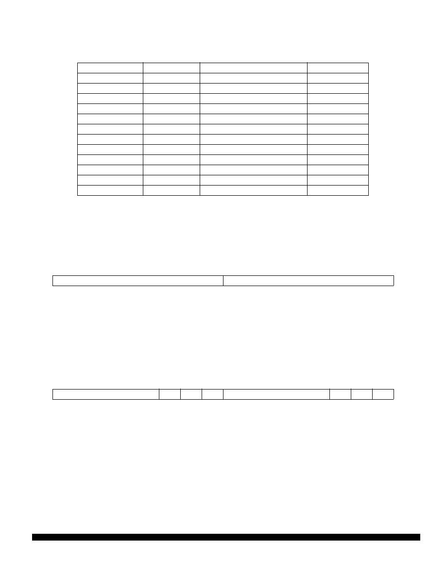
Table 45 GPT Interrupt Sources
Name
Source Number
Source
Vector Number
—
0000
Adjusted Channel
IVBA : 0000
IC1
0001
Input Capture 1
IVBA : 0001
IC2
0010
Input Capture 2
IVBA : 0010
IC3
0011
Input Capture 3
IVBA : 0011
OC1
0100
Output Compare 1
IVBA : 0100
OC2
0101
Output Compare 2
IVBA : 0101
OC3
0110
Output Compare 3
IVBA : 0110
OC4
0111
Output Compare 4
IVBA : 0111
IC4/OC5
1000
Input Capture 4/Output Compare 5
IVBA : 1000
TO
1001
Timer Overflow
IVBA : 1001
PAOV
1010
Pulse Accumulator Overflow
IVBA : 1010
PAI
1011
Pulse Accumulator Input
IVBA : 1011
DDRGP/PORTGP — Port GP Data Direction Register/Port GP Data Register
$YFF906
15
14
13
12
11
10
9
8
7
6
5
4
3
2
1
0
DDRGP
PORTGP
RESET:
0
OC1M/OC1D — OC1 Action Mask Register/OC1 Action Data Register
$YFF908
15
14
13
12
11
10
9
8
7
6
5
4
3
2
1
0
OC1M[5:1]
0
OC1D[5:1]
0
RESET:
0
F
re
e
sc
a
le
S
e
m
ic
o
n
d
u
c
to
r,
I
Freescale Semiconductor, Inc.
For More Information On This Product,
Go to: www.freescale.com
n
c
..
.
相關(guān)PDF資料 |
PDF描述 |
|---|---|
| SPMC916X1CTH16 | 16-BIT, FLASH, 16.78 MHz, MICROCONTROLLER, PQFP120 |
| MC68HCL05J1ADWR2 | 8-BIT, MROM, 2.1 MHz, MICROCONTROLLER, PDSO20 |
| MC68HC05J1AVDWR2 | 8-BIT, MROM, 2.1 MHz, MICROCONTROLLER, PDSO20 |
| MC68HCP11A1CFNE3 | 8-BIT, EEPROM, 3 MHz, MICROCONTROLLER, PQCC52 |
| MC68HLC705KJ1C | 8-BIT, OTPROM, 4 MHz, MICROCONTROLLER, PDIP16 |
相關(guān)代理商/技術(shù)參數(shù) |
參數(shù)描述 |
|---|---|
| MC92052 | 制造商:MOTOROLA 制造商全稱:Motorola, Inc 功能描述:FTTC User Framer |
| MC92053 | 制造商:MOTOROLA 制造商全稱:Motorola, Inc 功能描述:Quad FTTC Network Framer |
| MC92101CO | 制造商:Rochester Electronics LLC 功能描述:- Bulk |
| MC921G | 制造商:Rochester Electronics LLC 功能描述:- Bulk |
| MC92300 | 制造商:MOTOROLA 制造商全稱:Motorola, Inc 功能描述:VITERBI Decoder for Digital TV |
發(fā)布緊急采購(gòu),3分鐘左右您將得到回復(fù)。