- 您現(xiàn)在的位置:買賣IC網(wǎng) > PDF目錄371862 > HMS77C2001 [General Purpose(2) : ADC/ LED/ SCI/ PWM] PDF資料下載
參數(shù)資料
| 型號(hào): | HMS77C2001 |
| 英文描述: | [General Purpose(2) : ADC/ LED/ SCI/ PWM] |
| 中文描述: | [通用(2):藝術(shù)發(fā)展局/發(fā)光/工商/脈寬調(diào)制] |
| 文件頁(yè)數(shù): | 42/59頁(yè) |
| 文件大小: | 660K |
| 代理商: | HMS77C2001 |
第1頁(yè)第2頁(yè)第3頁(yè)第4頁(yè)第5頁(yè)第6頁(yè)第7頁(yè)第8頁(yè)第9頁(yè)第10頁(yè)第11頁(yè)第12頁(yè)第13頁(yè)第14頁(yè)第15頁(yè)第16頁(yè)第17頁(yè)第18頁(yè)第19頁(yè)第20頁(yè)第21頁(yè)第22頁(yè)第23頁(yè)第24頁(yè)第25頁(yè)第26頁(yè)第27頁(yè)第28頁(yè)第29頁(yè)第30頁(yè)第31頁(yè)第32頁(yè)第33頁(yè)第34頁(yè)第35頁(yè)第36頁(yè)第37頁(yè)第38頁(yè)第39頁(yè)第40頁(yè)第41頁(yè)當(dāng)前第42頁(yè)第43頁(yè)第44頁(yè)第45頁(yè)第46頁(yè)第47頁(yè)第48頁(yè)第49頁(yè)第50頁(yè)第51頁(yè)第52頁(yè)第53頁(yè)第54頁(yè)第55頁(yè)第56頁(yè)第57頁(yè)第58頁(yè)第59頁(yè)
HMS77C2000/2001
Nov. 2002 Ver 1.1
39
12.5 INTERNAL RESET TIMER (IRT)
In the HMS77C2000 and HMS77C2001, IRT runs from
RESET and varies based on oscillator selection (see Table
8-5.)
The IRT operates on an internal RC oscillator. The proces-
sor is kept in RESET as long as the IRT is active. The IRT
delay allows V
DD
to rise above V
DD
min., and for the os-
cillator to stabilize.
Oscillator circuits based on crystals or ceramic resonators
require a certain time after power-up to establish a stable
oscillation. The on-chip IRT keeps the device in a RESET
condition for approximately 18ms after RESET has
reached a logic high (V
IH
RESET) level. Thus, program-
ming UP3/RESET/V
PP
as RESET and using an external
RC network connected to the RESET input is not required
in most cases, allowing for savings in cost-sensitive and/or
space restricted applications, as well as allowing the use of
the UP3/RESET/V
PP
pin as a general purpose input.
The Device Reset time delay will vary from chip to chip
due to V
DD
, temperature, and process variation. See AC
parameters for details.
The IRT will also be triggered upon a Watchdog Timer
time-out. This is particularly important for applications us-
ing the WDT to wake from SLEEP mode automatically.
12.6 WATCHDOG TIMER (WDT)
The Watchdog Timer (WDT) is a free running on-chip RC
oscillator which does not require any external components.
This RC oscillator is separate from the external RC oscil-
lator of the UP5/X
IN
pin and the internal 4 MHz oscillator.
That means that the WDT will run even if the main proces-
sor clock has been stopped, for example, by execution of a
SLEEP
instruction. During normal operation or SLEEP, a
WDT reset or wake-up reset generates a device RESET.
The TO bit (STATUS<4>) will be cleared upon a Watch-
dog Timer reset. The WDT can be permanently disabled
by programming the configuration bit WDTE as a ‘0’ (Sec-
tion 8.1). Refer to the HMS77C2000 and HMS77C2001
Programming Specifications to determine how to access
the configuration word.
12.6.1 WDT PERIOD
The WDT has a nominal time-out period of 18 ms, (with
no prescaler). If a longer time-out period is desired, a pres-
caler with a division ratio of up to 1:128 can be assigned to
the WDT (under software control) by writing to the OP-
TION register. Thus, a time-out period of a nominal 2.3
seconds can be realized. These periods vary with tempera-
ture, V
DD
and part-to-part process variations (see DC
specs).
Under worst case conditions (V
DD
= Min., Temperature =
Max., max. WDT prescaler), it may take several seconds
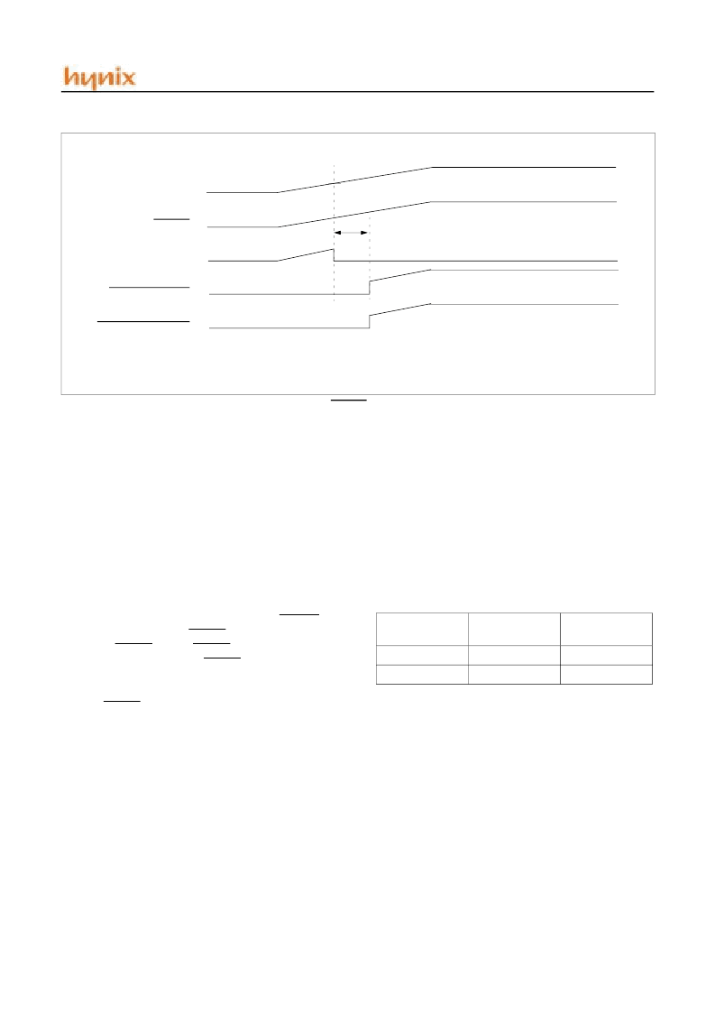
FIGURE 12-9 TIME-OUT SEQUENCE ON POWER-UP(RESET TIED TO V
DD
): SLOW V
DD
RISE TIME
V
DD
RESET
INTERNAL POR
IRT TIMER-OUT
INTERNAL RESET
T
IRT
Oscillator
Configuration
POR Reset
Subsequent
Resets
IRC & ERC
18 ms(typ.)
300us(typ.)
XT & LF
18 ms(typ.)
18ms(typ.)
TABLE 12-5 IRT(INTERNAL RESET TIMER PERIOD)
相關(guān)PDF資料 |
PDF描述 |
|---|---|
| HMS81004 | REMOTE CONTROLLER |
| HMS81008 | siHYNIX SEMICONDUCTOR 8-BIT SINGLE-CHIP MICROCONTROLLERS |
| HMS81016 | REMOTE CONTROLLER |
| HMS81020ET | REMOTE CONTROLLER |
| HMS81024 | REMOTE CONTROLLER |
相關(guān)代理商/技術(shù)參數(shù) |
參數(shù)描述 |
|---|---|
| HMS81004 | 制造商:未知廠家 制造商全稱:未知廠家 功能描述:REMOTE CONTROLLER |
| HMS81004E | 制造商:HYNIX 制造商全稱:Hynix Semiconductor 功能描述:HYNIX SEMICONDUCTOR 8-BIT SINGLE-CHIP MICROCONTROLLERS |
| HMS81008 | 制造商:未知廠家 制造商全稱:未知廠家 功能描述:REMOTE CONTROLLER |
| HMS81008E | 制造商:HYNIX 制造商全稱:Hynix Semiconductor 功能描述:HYNIX SEMICONDUCTOR 8-BIT SINGLE-CHIP MICROCONTROLLERS |
| HMS81016 | 制造商:未知廠家 制造商全稱:未知廠家 功能描述:REMOTE CONTROLLER |
發(fā)布緊急采購(gòu),3分鐘左右您將得到回復(fù)。