- 您現(xiàn)在的位置:買賣IC網(wǎng) > PDF目錄366550 > AM79C970 (Advanced Micro Devices, Inc.) PCnetTM-PCI Single-Chip Ethernet Controller for PCI Local Bus PDF資料下載
參數(shù)資料
| 型號: | AM79C970 |
| 廠商: | Advanced Micro Devices, Inc. |
| 英文描述: | PCnetTM-PCI Single-Chip Ethernet Controller for PCI Local Bus |
| 中文描述: | PCnetTM - PCI單芯片以太網(wǎng)控制器的PCI總線 |
| 文件頁數(shù): | 62/168頁 |
| 文件大小: | 943K |
| 代理商: | AM79C970 |
第1頁第2頁第3頁第4頁第5頁第6頁第7頁第8頁第9頁第10頁第11頁第12頁第13頁第14頁第15頁第16頁第17頁第18頁第19頁第20頁第21頁第22頁第23頁第24頁第25頁第26頁第27頁第28頁第29頁第30頁第31頁第32頁第33頁第34頁第35頁第36頁第37頁第38頁第39頁第40頁第41頁第42頁第43頁第44頁第45頁第46頁第47頁第48頁第49頁第50頁第51頁第52頁第53頁第54頁第55頁第56頁第57頁第58頁第59頁第60頁第61頁當(dāng)前第62頁第63頁第64頁第65頁第66頁第67頁第68頁第69頁第70頁第71頁第72頁第73頁第74頁第75頁第76頁第77頁第78頁第79頁第80頁第81頁第82頁第83頁第84頁第85頁第86頁第87頁第88頁第89頁第90頁第91頁第92頁第93頁第94頁第95頁第96頁第97頁第98頁第99頁第100頁第101頁第102頁第103頁第104頁第105頁第106頁第107頁第108頁第109頁第110頁第111頁第112頁第113頁第114頁第115頁第116頁第117頁第118頁第119頁第120頁第121頁第122頁第123頁第124頁第125頁第126頁第127頁第128頁第129頁第130頁第131頁第132頁第133頁第134頁第135頁第136頁第137頁第138頁第139頁第140頁第141頁第142頁第143頁第144頁第145頁第146頁第147頁第148頁第149頁第150頁第151頁第152頁第153頁第154頁第155頁第156頁第157頁第158頁第159頁第160頁第161頁第162頁第163頁第164頁第165頁第166頁第167頁第168頁
P R E L I M I N A R Y
AMD
1-929
Am79C970
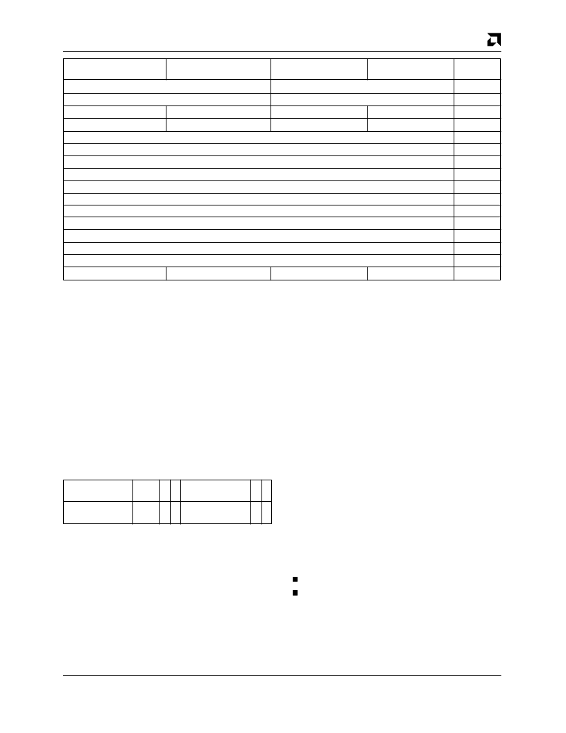
Device ID
Status
Vendor ID
Command
00h
04h
08h
0Ch
10h
14h
18h
1Ch
20h
24h
28h
2Ch
30h
34h
38h
3Ch
Base-Class
Reserved
Sub-Class
Header Type
Programming IF
Latency Timer
Revision ID
Reserved
Base Address
Reserved
Reserved
Reserved
Reserved
Reserved
Reserved
Reserved
Reserved
Reserved
Reserved
Reserved
Reserved
Interrupt Pin
Interrupt Line
31
24 23
16
15
8
7
0
Offset
The configuration registers are accessible only by PCI
configuration cycles. They can be accessed right after
the PCnet-PCI controller is powered-on, even if the read
operation of the serial EEPROM is still on-going. All
multi-byte numeric fields follow little endian byte order-
ing. The Command register is the only register cleared
by H_RESET. S_RESET as well as asserting
SLEEP
have no effect on the value of the PCI configuration reg-
isters. All write accesses to Reserved locations have no
effect, reads from these locations will return a data value
of ZERO.
When the PCnet-PCI controller samples its IDSEL input
asserted during a configuration cycle, it will acknowl-
edge the cycle by asserting its
DEVSEL
output. The
content of AD[31:00] during the address phase of the
configuration cycles must meet the format as shown
below:
Don’t
Care
Don’t Care
0 0
DWORD Index
0 0
31
11 10
8 7
6 5
2 1 0
AD[1:0] must both be ZEROs, since the PCnet-PCI con-
troller is not a bridge device. It only recognizes configu-
ration cycles of Type 0 (as defined by the PCI
specification revision 2.0). AD[7:2] specify the selected
DWORD in the configuration space. AD[7:6] must both
be ZERO, since the PCnet-PCI controller does not im-
plement any of the device specific registers in locations
64 – 255. Since AD[1:0] and AD[7:6] must all be ZERO,
the lower 8 bits of the address for a configuration cycle
are equal to the offset of the DWORD counting from the
beginning of the PCI configuration space. AD[10:8]
specify one of eight possible functions of a PCI device.
The PCnet-PCI controller is a single function device, as
indicated in the Header Type register of its PCI configu-
ration space (bit 7, FUNCT = 0). Therefore, the PCnet-
PCI controller ignores AD[10:8] during the address
phase of a configuration cycle. AD[31:11] are typically
troller ignores all upper address bits.
PCI configuration registers can be accessed with 8-bit,
16-bit or 32-bit transfers. The active bytes within a
DWORD are determined by the byte enable signals.
E.G. a read of the Sub-Class register can be performed
by reading from offset 08h with only
BE
2 being active.
I/O Resources
PCnet-PCI Controller I/O Resource Mapping
The PCnet-PCI controller has several I/O resources.
These resources use 32 bytes of I/O space that begin at
the PCnet-PCI controller I/O base address.
The PCnet-PCI controller allows two modes of slave ac-
cess. Word I/O mode treats all PCnet-PCI controller I/O
Resources as two-byte entities spaced at two-byte ad-
dress intervals. Double Word I/O mode treats all PCnet-
PCI controller I/O Resources as four-byte entities
spaced at four-byte address intervals. The selection of
WIO or DWIO mode is accomplished by one of
two ways:
H_RESET function.
Automatic determination of DWIO mode due to
DWORD (double-word) I/O write access to offset
10h.
The PCnet-PCI controller I/O mode setting will default to
WIO after H_RESET (i.e. DWIO = 0).
相關(guān)PDF資料 |
PDF描述 |
|---|---|
| AM79C971VCW | PCnet⑩-FAST Single-Chip Full-Duplex 10/100 Mbps Ethernet Controller for PCI Local Bus |
| AM79C971 | PCnet⑩-FAST Single-Chip Full-Duplex 10/100 Mbps Ethernet Controller for PCI Local Bus |
| AM79C971KCW | IC LOGIC 16211 24-BIT FET BUS SWITCH -40+85C TSSOP-56 35/TUBE |
| AM79C972BKCW | PCnet⑩-FAST+ Enhanced 10/100 Mbps PCI Ethernet Controller with OnNow Support |
| AM79C972BKIW | PCnet⑩-FAST+ Enhanced 10/100 Mbps PCI Ethernet Controller with OnNow Support |
相關(guān)代理商/技術(shù)參數(shù) |
參數(shù)描述 |
|---|---|
| AM79C970A | 制造商:AMD 制造商全稱:Advanced Micro Devices 功能描述:PCnet-PCI II Single-Chip Full-Duplex Ethernet Controller for PCI Local Bus Product |
| AM79C970AKC | 制造商:AMD 制造商全稱:Advanced Micro Devices 功能描述:PCnet-PCI II Single-Chip Full-Duplex Ethernet Controller for PCI Local Bus Product |
| AM79C970AKC\\W | 制造商:Rochester Electronics LLC 功能描述:- Bulk 制造商:Advanced Micro Devices 功能描述: |
| AM79C970AKC\W | 制造商:Rochester Electronics LLC 功能描述:- Bulk |
發(fā)布緊急采購,3分鐘左右您將得到回復(fù)。