- 您現(xiàn)在的位置:買賣IC網(wǎng) > PDF目錄376461 > XRT72L74 (Exar Corporation) Ultraframer DS3/E3/DS2/E2/DS1/E1/DS0 PDF資料下載
參數(shù)資料
| 型號: | XRT72L74 |
| 廠商: | Exar Corporation |
| 元件分類: | 通信及網(wǎng)絡(luò) |
| 英文描述: | Ultraframer DS3/E3/DS2/E2/DS1/E1/DS0 |
| 中文描述: | Ultraframer DS3/E3/DS2/E2/DS1/E1/DS0 |
| 文件頁數(shù): | 54/104頁 |
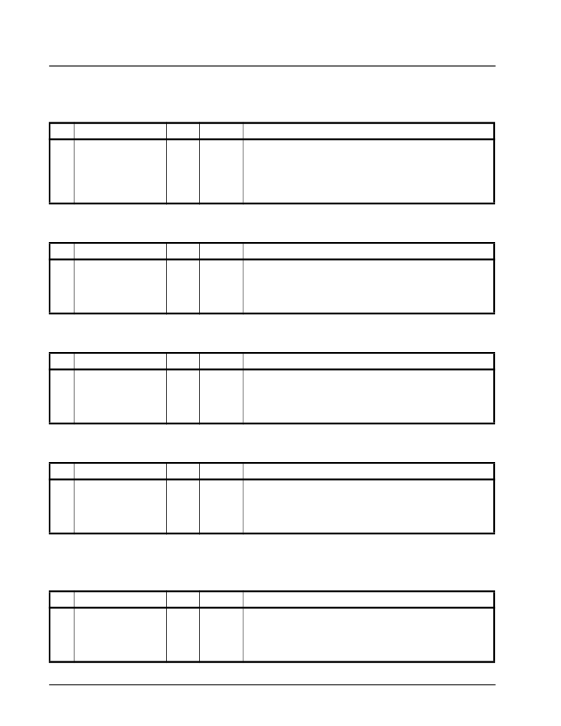
| 文件大小: | 1301K |
| 代理商: | XRT72L74 |
第1頁第2頁第3頁第4頁第5頁第6頁第7頁第8頁第9頁第10頁第11頁第12頁第13頁第14頁第15頁第16頁第17頁第18頁第19頁第20頁第21頁第22頁第23頁第24頁第25頁第26頁第27頁第28頁第29頁第30頁第31頁第32頁第33頁第34頁第35頁第36頁第37頁第38頁第39頁第40頁第41頁第42頁第43頁第44頁第45頁第46頁第47頁第48頁第49頁第50頁第51頁第52頁第53頁當(dāng)前第54頁第55頁第56頁第57頁第58頁第59頁第60頁第61頁第62頁第63頁第64頁第65頁第66頁第67頁第68頁第69頁第70頁第71頁第72頁第73頁第74頁第75頁第76頁第77頁第78頁第79頁第80頁第81頁第82頁第83頁第84頁第85頁第86頁第87頁第88頁第89頁第90頁第91頁第92頁第93頁第94頁第95頁第96頁第97頁第98頁第99頁第100頁第101頁第102頁第103頁第104頁

XRT72L74
FOUR CHANNEL, DS3 ATM UNI/CLEAR-CHANNEL FRAMER
REV. P1.0.0
á
PRELIMINARY
54
T
ABLE
8:
T
EST
C
ELL
E
RROR
A
CCUMULATOR
H
OLDING
R
EGISTER
R
EGISTER
7 T
EST
C
ELL
E
RROR
A
CCUMULATOR
H
OLDING
R
EGISTER
H
EX
A
DDRESS
: 0
X
07
B
IT
F
UNCTION
T
YPE
D
EFAULT
D
ESCRIPTION
-O
PERATION
7-0
TEST CELL HOLDING
REGISTER
RO
0x00
Holds the “Unread” byte of the 16-bit Test Cell Error Accumulator, when that
register is read. The XRT72L74 will transfer the contents of the “Unread”
byte to this “Holding” register, anytime the Bidirectional Data Bus (of the
Microprocessor Interface) is configured to be 8-bits wide.
N
OTE
:
This register is only active if the XRT72L74 has been configured to
operate in the “ATM UNI” Mode.
T
ABLE
9:
T
EST
C
ELL
H
EADER
B
YTE
-1
R
EGISTER
8 T
EST
C
ELL
H
EADER
B
YTE
-1 H
EX
A
DDRESS
: 0
X
08
B
IT
F
UNCTION
T
YPE
D
EFAULT
D
ESCRIPTION
-O
PERATION
7-0
TEST CELL HEADER
BYTE 1
R/W
0x11
Test Cell Header Byte - 1
Permits the user to define the value of “Header Byte # 1” within each Test Cell
which is generated by the “Test Cell Generator”.
N
OTE
:
This register is only active if the XRT72L74 has been configured to
operate in the “ATM UNI” Mode.
T
ABLE
10:
T
EST
C
ELL
H
EADER
B
YTE
-2
R
EGISTER
9 T
EST
C
ELL
H
EADER
B
YTE
-2 H
EX
A
DDRESS
: 0
X
09
B
IT
F
UNCTION
T
YPE
D
EFAULT
D
ESCRIPTION
-O
PERATION
7-0
TEST CELL HEADER
BYTE 2
R/W
0x22
Test Cell Header Byte - 2
Permits the user to define the value of “Header Byte # 2” within each Test Cell
which is generated by the “Test Cell Generator”.
N
OTE
:
This register is only active if the XRT72L74 has been configured to
operate in the “ATM UNI” Mode.
T
ABLE
11:
T
EST
C
ELL
H
EADER
B
YTE
-3
R
EGISTER
10 T
EST
C
ELL
H
EADER
B
YTE
-3 H
EX
A
DDRESS
: 0
X
0A
B
IT
F
UNCTION
T
YPE
D
EFAULT
D
ESCRIPTION
-O
PERATION
7-0
TEST CELL HEADER
BYTE 3
R/W
0x33
Test Cell Header Byte - 3
Permits the user to define the value of “Header Byte # 3” within each Test Cell
which is generated by the “Test Cell Generator”.
N
OTE
:
This register is only active if the XRT72L74 has been configured to
operate in the “ATM UNI” Mode.
T
ABLE
12:
T
EST
C
ELL
H
EADER
B
YTE
-4
R
EGISTER
11 T
EST
C
ELL
H
EADER
B
YTE
-4 H
EX
A
DDRESS
: 0
X
0B
B
IT
F
UNCTION
T
YPE
D
EFAULT
D
ESCRIPTION
-O
PERATION
7-0
TEST CELL HEADER
BYTE 4
R/W
0x44
Test Cell Header Byte - 4
Permits the user to define the value of “Header Byte # 4” within each Test Cell
which is generated by the “Test Cell Generator”.
N
OTE
:
This register is only active if the XRT72L74 has been configured to
operate in the “ATM UNI” Mode.
相關(guān)PDF資料 |
PDF描述 |
|---|---|
| XRT7300IV | E3/DS3/STS-1 LINE INTERFACE UNIT |
| XRT7300 | E3/DS3/STS-1 LINE INTERFACE UNIT |
| XRT7302 | 2 Channel E3/DS3/STS-1 Line Interface Unit(2通道 E3/DS3/STS-1線接口單元) |
| XRT73L02M | TWO CHANNEL E3/DS3/STS-1 LINE INTERFACE UNIT |
| XRT73L02MIV | TWO CHANNEL E3/DS3/STS-1 LINE INTERFACE UNIT |
相關(guān)代理商/技術(shù)參數(shù) |
參數(shù)描述 |
|---|---|
| XRT72L74IB | 制造商:未知廠家 制造商全稱:未知廠家 功能描述:Telecommunication IC |
| XRT7300 | 制造商:EXAR 制造商全稱:EXAR 功能描述:E3/DS3/STS-1 LINE INTERFACE UNIT |
| XRT7300ES | 功能描述:網(wǎng)絡(luò)控制器與處理器 IC RoHS:否 制造商:Micrel 產(chǎn)品:Controller Area Network (CAN) 收發(fā)器數(shù)量: 數(shù)據(jù)速率: 電源電流(最大值):595 mA 最大工作溫度:+ 85 C 安裝風(fēng)格:SMD/SMT 封裝 / 箱體:PBGA-400 封裝:Tray |
| XRT7300IV | 功能描述:外圍驅(qū)動(dòng)器與原件 - PCI . . RoHS:否 制造商:PLX Technology 工作電源電壓: 最大工作溫度: 安裝風(fēng)格:SMD/SMT 封裝 / 箱體:FCBGA-1156 封裝:Tray |
| XRT7300IV-F | 功能描述:外圍驅(qū)動(dòng)器與原件 - PCI RoHS:否 制造商:PLX Technology 工作電源電壓: 最大工作溫度: 安裝風(fēng)格:SMD/SMT 封裝 / 箱體:FCBGA-1156 封裝:Tray |
發(fā)布緊急采購,3分鐘左右您將得到回復(fù)。