- 您現(xiàn)在的位置:買賣IC網(wǎng) > PDF目錄385949 > TSB81BA3I (Texas Instruments, Inc.) IEEE 1394b THREE-PORT CABLE TRANSCEIVER/ARBITER PDF資料下載
參數(shù)資料
| 型號: | TSB81BA3I |
| 廠商: | Texas Instruments, Inc. |
| 英文描述: | IEEE 1394b THREE-PORT CABLE TRANSCEIVER/ARBITER |
| 中文描述: | 的IEEE 1394b三端口電纜收發(fā)器/仲裁者 |
| 文件頁數(shù): | 15/57頁 |
| 文件大小: | 810K |
| 代理商: | TSB81BA3I |
第1頁第2頁第3頁第4頁第5頁第6頁第7頁第8頁第9頁第10頁第11頁第12頁第13頁第14頁當前第15頁第16頁第17頁第18頁第19頁第20頁第21頁第22頁第23頁第24頁第25頁第26頁第27頁第28頁第29頁第30頁第31頁第32頁第33頁第34頁第35頁第36頁第37頁第38頁第39頁第40頁第41頁第42頁第43頁第44頁第45頁第46頁第47頁第48頁第49頁第50頁第51頁第52頁第53頁第54頁第55頁第56頁第57頁
SLLS559B DECEMBER 2002 REVISED OCTOBER 2003
15
POST OFFICE BOX 655303
DALLAS, TEXAS 75265
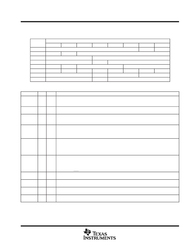
APPLICATION INFORMATION
Table 1. Base Register Configuration
Address
BIT POSITION
3
0
1
2
4
5
6
7
0000
Physical ID
R
CPS
0001
RHB
IBR
Gap_Count
0010
Extended (111b)
Num_Ports (0011b)
0011
PHY_Speed (111b)
Rsvd
Delay (0000b)
0100
LCtrl
C
Jitter (000b)
Pwr_Class
0101
WDIE
ISBR
CTOI
CPSI
STOI
PEI
EAA
EMC
0110
Max Legacy SPD
BLINK
Bridge
Rsvd
0111
Page_Select
Rsvd
Port_Select
Table 2. Base Register Field Descriptions
FIELD
SIZE
TYPE
DESCRIPTION
Physical ID
6
Rd
This field contains the physical address ID of this node determined during self-ID. The physical-ID is invalid after
a bus reset until the self-ID has completed as indicated by an unsolicited register 0 status transfer from the PHY
to the LLC.
R
1
Rd
Root. This bit indicates that this node is the root node. The R bit is reset to 0 by bus reset, and is set to 1 during
tree-ID if this node becomes root.
CPS
1
Rd
Cable-power-status. This bit indicates the state of the CPS input terminal. The CPS terminal is normally tied to
serial bus cable power through a 400-k
resistor. A 0 in this bit indicates that the cable power voltage has
dropped below its threshold for ensured reliable operation.
RHB
1
Rd/Wr
Root-holdoff bit. This bit instructs the PHY to attempt to become root after the next bus reset. The RHB bit is reset
to 0 by a hardware reset, and is unaffected by a bus reset. If two nodes on a single bus have their root holdoff bit
set, then the result is not defined. To prevent two nodes from having their root-holdoff bit set, this bit must only be
written using a PHY configuration packet.
Initiate bus reset. This bit instructs the PHY to initiate a long (166
μ
s) bus reset at the next opportunity. Any
receive or transmit operation in progress when this bit is set completes before the bus reset is initiated. The IBR
bit is reset to 0 after a hardware reset or a bus reset. Care must be exercised when writing to this bit to not change
the other bits in this register. It is recommended that whenever possible a bus reset be initiated using the ISBR bit
and not the IBR bit.
IBR
1
Rd/Wr
Gap_Count
6
Rd/Wr
Arbitration gap count. This value sets the subaction (fair) gap, arb-reset gap, and arb-delay times. The gap count
can be set either by a write to the register, or by reception or transmission of a PHY_CONFIG packet. The gap
count is reset to 3Fh by hardware reset or after two consecutive bus resets without an intervening write to the gap
count register (either by a write to the PHY register or by a PHY_CONFIG packet).
It is strongly recommended
that this field only be changed using PHY configuration packets.
Extended register definition. For the TSB81BA3, this field is 111b, indicating that the extended register set is
implemented.
Extended
3
Rd
Num_Ports
4
Rd
Number of ports. This field indicates the number of ports implemented in the PHY. For the TSB81BA3 this field is
3.
PHY_Speed
3
Rd
PHY speed capability. This field is no longer used. For the TSB81BA3 PHY this field is 111b. Speeds for 1394b
PHYs must be checked on a port-by-port basis.
Delay
4
Rd
PHY repeater data delay. This field indicates the worst case repeater data delay of the PHY, expressed as
144+(delay
×
20) ns. For the TSB81BA3 this field is 0.
相關PDF資料 |
PDF描述 |
|---|---|
| TSE-0155-32S-P1-3 | SINGLE MODE SINGLE FIBER TRANSCEIVER |
| TSL230 | PROGRAMMABLE LIGHT-TO-FREQUENCY CONVERTERS |
| TSL235(中文) | Programmable Light-To-Frequency Converter(光頻轉(zhuǎn)換器) |
| TSL245(中文) | IR Light-To-Frequency Converter(紅外光頻轉(zhuǎn)換器) |
| TSL250(中文) | Light-To-Voltage Converter(光壓轉(zhuǎn)換器) |
相關代理商/技術參數(shù) |
參數(shù)描述 |
|---|---|
| TSB81BA3IPFP | 功能描述:射頻收發(fā)器 s800 3-Port Cable Xcvr/Arbiter RoHS:否 制造商:Atmel 頻率范圍:2322 MHz to 2527 MHz 最大數(shù)據(jù)速率:2000 Kbps 調(diào)制格式:OQPSK 輸出功率:4 dBm 類型: 工作電源電壓:1.8 V to 3.6 V 最大工作溫度:+ 85 C 接口類型:SPI 封裝 / 箱體:QFN-32 封裝:Tray |
| TSB81BA3IPFPEP | 功能描述:射頻收發(fā)器 Mil Enh 3-Port Cable Xcvr/Arbiter RoHS:否 制造商:Atmel 頻率范圍:2322 MHz to 2527 MHz 最大數(shù)據(jù)速率:2000 Kbps 調(diào)制格式:OQPSK 輸出功率:4 dBm 類型: 工作電源電壓:1.8 V to 3.6 V 最大工作溫度:+ 85 C 接口類型:SPI 封裝 / 箱體:QFN-32 封裝:Tray |
| TSB81BA3PFP | 功能描述:射頻收發(fā)器 s800 3-Port Cable Xcvr/Arbiter RoHS:否 制造商:Atmel 頻率范圍:2322 MHz to 2527 MHz 最大數(shù)據(jù)速率:2000 Kbps 調(diào)制格式:OQPSK 輸出功率:4 dBm 類型: 工作電源電壓:1.8 V to 3.6 V 最大工作溫度:+ 85 C 接口類型:SPI 封裝 / 箱體:QFN-32 封裝:Tray |
| TSB81BA3PFPG4 | 功能描述:射頻收發(fā)器 s800 3-Port Cable Xcvr/Arbiter RoHS:否 制造商:Atmel 頻率范圍:2322 MHz to 2527 MHz 最大數(shù)據(jù)速率:2000 Kbps 調(diào)制格式:OQPSK 輸出功率:4 dBm 類型: 工作電源電壓:1.8 V to 3.6 V 最大工作溫度:+ 85 C 接口類型:SPI 封裝 / 箱體:QFN-32 封裝:Tray |
| TSB82AA2 | 制造商:TI 制造商全稱:Texas Instruments 功能描述:1394b OHCI-LYNX CONTROLLER |
發(fā)布緊急采購,3分鐘左右您將得到回復。