- 您現(xiàn)在的位置:買賣IC網(wǎng) > PDF目錄295865 > E28F320J5-120 (INTEL CORP) StrataFlash MEMORY TECHNOLOGY 32 AND 64 MBIT PDF資料下載
參數(shù)資料
| 型號: | E28F320J5-120 |
| 廠商: | INTEL CORP |
| 元件分類: | PROM |
| 英文描述: | StrataFlash MEMORY TECHNOLOGY 32 AND 64 MBIT |
| 中文描述: | 2M X 16 FLASH 5V PROM, 150 ns, PDSO56 |
| 封裝: | 14 X 20 MM, TSOP-56 |
| 文件頁數(shù): | 24/51頁 |
| 文件大?。?/td> | 651K |
| 代理商: | E28F320J5-120 |
第1頁第2頁第3頁第4頁第5頁第6頁第7頁第8頁第9頁第10頁第11頁第12頁第13頁第14頁第15頁第16頁第17頁第18頁第19頁第20頁第21頁第22頁第23頁當(dāng)前第24頁第25頁第26頁第27頁第28頁第29頁第30頁第31頁第32頁第33頁第34頁第35頁第36頁第37頁第38頁第39頁第40頁第41頁第42頁第43頁第44頁第45頁第46頁第47頁第48頁第49頁第50頁第51頁
28F320J5 and 28F640J5
30
Datasheet
NOTE:
1. When the device is configured in one of the pulse modes, the STS pin pulses low with a typical pulse width of
250 ns.
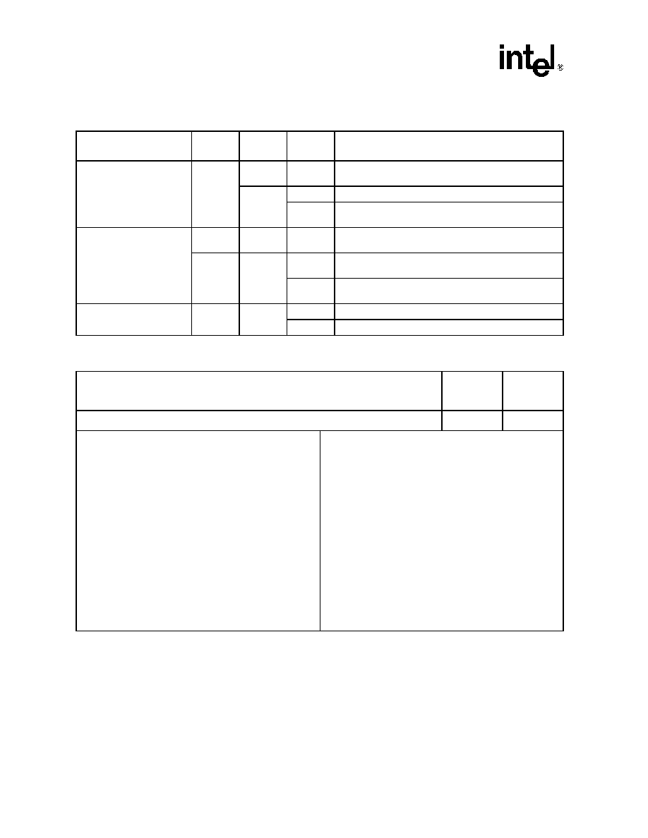
Table 15. Write Protection Alternatives
Operation
Master
Lock-Bit
Block
Lock-Bit
RP#
Effect
Block Erase or Program
0
VIH or
VHH
Block Erase and Program Enabled
X1
VIH
Block is Locked. Block Erase and Program Disabled
VHH
Block Lock-Bit Override. Block Erase and Program
Enabled
Set or Clear Block Lock-Bits
0
X
VIH or
VHH
Set or Clear Block Lock-Bit Enabled
1X
VIH
Master Lock-Bit Is Set. Set or Clear Block Lock-Bit
Disabled
VHH
Master Lock-Bit Override. Set or Clear Block Lock-Bit
Enabled
Set Master Lock-Bit
X
VIH
Set Master Lock-Bit Disabled
VHH
Set Master Lock-Bit Enabled
Table 16. Configuration Coding Definitions
Reserved
Pulse on
Program
Complete(1)
Pulse on
Erase
Complete(1)
Bits 7—2
Bit 1
Bit 0
DQ7–DQ2 = Reserved
DQ1–DQ0 = STS Pin Configuration Codes
00 = default, level mode RY/BY#
(device ready) indication
01 = pulse on Erase complete
10 = pulse on Program complete
11 = pulse on Erase or Program Complete
Configuration Codes 01b, 10b, and 11b are all pulse mode
such that the STS pin pulses low then high when the operation
indicated by the given configuration is completed.
Configuration Command Sequences for STS pin configuration
(maskingbits DQ7–DQ2 to 00h) are as follows:
Default RY/BY# level mode: B8h, 00h
ER INT (Erase Interrupt): B8h, 01h
Pulse-on-Erase Complete
PR INT (Program Interrupt): B8h, 02h
Pulse-on-Program Complete
ER/PR INT (Erase or Program Interrupt): B8h, 03h
Pulse-on-Erase or Program Complete
DQ7–DQ2 are reserved for future use.
default (DQ1–DQ0 = 00) RY/BY#, level mode
— usedtocontrol HOLD toamemorycontroller toprevent
accessinga flash memory subsystem while any flash device's
WSM is busy.
configuration 01 ER INT, pulse mode
— used to generate a system interrupt pulse when any flash
device in an array has completed a Block Erase or sequence of
Queued Block Erases. Helpful for reformattingblocks after file
system free space reclamation or “cleanup”
configuration 10 PR INT, pulse mode
— used to generate a system interrupt pulse when any flash
device in an array has complete a Program operation. Provides
highest performance for servicing continuous buffer write
operations.
configuration 11 ER/PR INT, pulse mode
— used to generate system interrupts to trigger servicing of
flash arrays when either erase or program operations are
completed when a common interrupt service routine is desired.
相關(guān)PDF資料 |
PDF描述 |
|---|---|
| E28F400BX-B120 | 4-MBIT (256K X 16, 512K X 8) BOOT BLOCK FLASH MEMORY FAMILY |
| E28F400BX-B60 | ACTUATOR, SWITCH, ROUND, MOMENTARY; Approval Bodies:BEAB, VDE, UL, CSA; Diameter, external:29mm; IP rating:65; Operations, mechanical No. of:1000000; Temp, op. max:85(degree C); Temp, op. min:-20(degree C) RoHS Compliant: Yes |
| E28F400BX-B80 | 4-MBIT (256K X 16, 512K X 8) BOOT BLOCK FLASH MEMORY FAMILY |
| E28F400BX-T120 | 4-MBIT (256K X 16, 512K X 8) BOOT BLOCK FLASH MEMORY FAMILY |
| E28F004BX-T120 | OSC 5V SMT PLAS 14X9 CMOS |
相關(guān)代理商/技術(shù)參數(shù) |
參數(shù)描述 |
|---|---|
| E28F320J5A-120 | 制造商:Intel 功能描述: |
| E28F320S5-110 | 制造商:INTEL 制造商全稱:Intel Corporation 功能描述:WORD-WIDE FlashFile MEMORY FAMILY |
| E28F320S5-90 | 制造商:INTEL 制造商全稱:Intel Corporation 功能描述:WORD-WIDE FlashFile MEMORY FAMILY |
| E28F400B5B60 | 制造商:INTEL 制造商全稱:Intel Corporation 功能描述:SMART 5 BOOT BLOCK FLASH MEMORY FAMILY 2, 4, 8 MBIT |
| E28F400B5B80 | 制造商:Rochester Electronics LLC 功能描述: 制造商:Intel 功能描述: |
發(fā)布緊急采購,3分鐘左右您將得到回復(fù)。