- 您現(xiàn)在的位置:買賣IC網(wǎng) > PDF目錄378216 > 82557 (Intel Corp.) Fast Ethernet PCI Bus Controller(快速以太網(wǎng) PCI總線控制器) PDF資料下載
參數(shù)資料
| 型號: | 82557 |
| 廠商: | Intel Corp. |
| 英文描述: | Fast Ethernet PCI Bus Controller(快速以太網(wǎng) PCI總線控制器) |
| 中文描述: | 快速以太網(wǎng)PCI總線控制器(快速以太網(wǎng)的PCI總線控制器) |
| 文件頁數(shù): | 38/57頁 |
| 文件大小: | 601K |
| 代理商: | 82557 |
第1頁第2頁第3頁第4頁第5頁第6頁第7頁第8頁第9頁第10頁第11頁第12頁第13頁第14頁第15頁第16頁第17頁第18頁第19頁第20頁第21頁第22頁第23頁第24頁第25頁第26頁第27頁第28頁第29頁第30頁第31頁第32頁第33頁第34頁第35頁第36頁第37頁當(dāng)前第38頁第39頁第40頁第41頁第42頁第43頁第44頁第45頁第46頁第47頁第48頁第49頁第50頁第51頁第52頁第53頁第54頁第55頁第56頁第57頁
INTEL 82557 FAST ETHERNET PCI BUS CONTROLLER
38
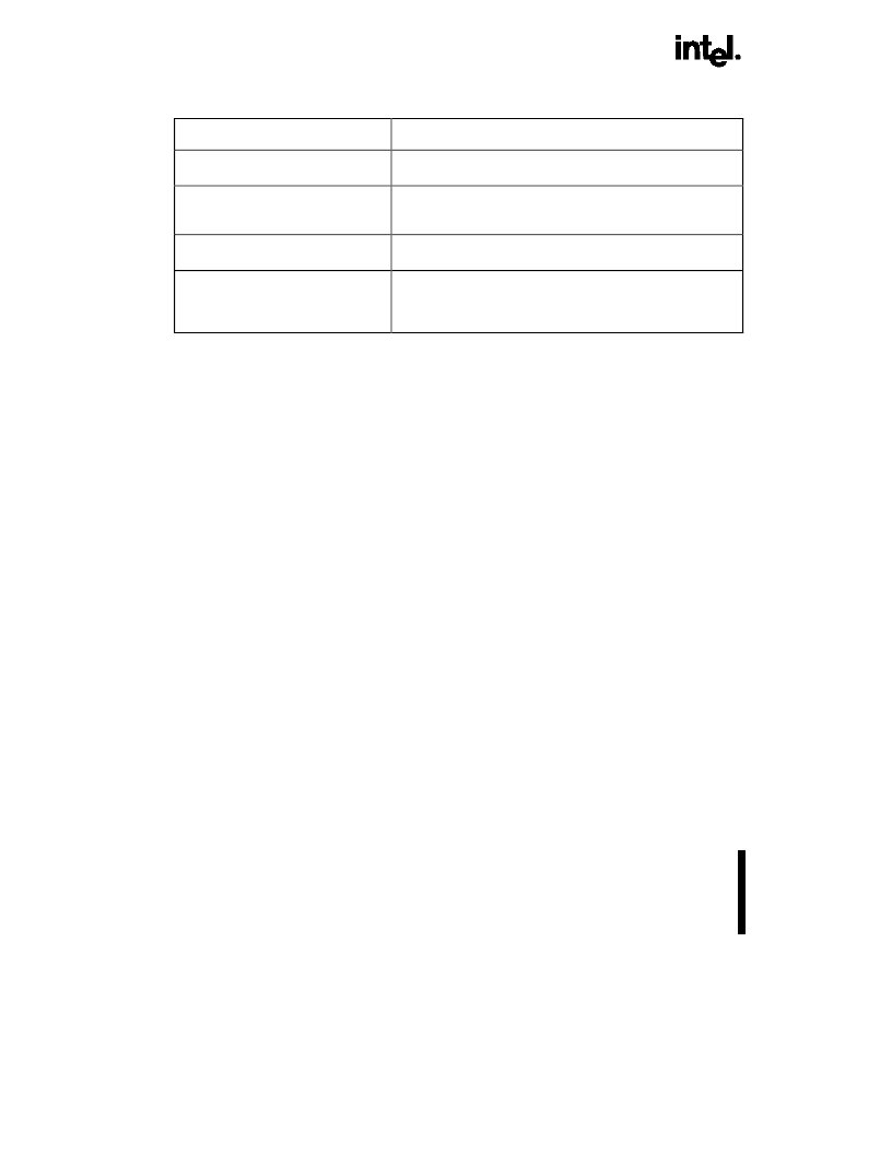
Table 8. Summary of Reset Commands
RESET Operation
Effect On 82557
Hardware reset
Resets all internal registers. A full initialization sequence is needed
to make the 82557 operational.
Software reset
*
(issued as PORT
RESET
**
command)
Resets all internal registers except the PCI configuration registers.
A full initialization sequence is needed to make the 82557
operational.
Selective Reset (issued as PORT
SELECTIVE RESET
**
command)
Maintains configuration information. All other setup information is
lost.
Self Test (issued as a PORT SELF
TEST
**
command) or PORT DUMP
command
Resets all internal registers. A Selective Reset is issued internally
before the command is executed. A Software Reset is issued
internally after the command is completed. A full initialization
sequence is needed to make the 82557 operational.
NOTES:
* Software reset will be used throughout this manual to indicate a complete reset using the PORT reset command.
** PORT commands are discussed in detail in the
82557 User’s Manual
.
5.2.
Initializing the 82557
A power-on or software reset prepares the 82557 for
normal operation. Because the PCI specification
already provides for auto-configuration of many
critical parameters such as I/O, memory mapping
and interrupt assignment, the 82557 is set to an
operational default state after reset. However, the
82557 cannot transmit or receive frames until a
Configure command is issued. Refer to the
82557
User’s Manual
for additional information. Table 6 lists
the different reset options.
5.3.
Controlling the 82557
The CPU issues control commands to the Command
Unit (CU) and Receive Unit (RU) through the SCB,
which is part of the CSR (described below). The CPU
instructs the 82557 to Activate, Suspend, Resume or
Idle the CU or RU by placing the appropriate control
command in the CU or RU control field. A CPU write
access to the SCB causes the 82557 to read the
SCB, including the Status word, Command word, CU
and RU Control fields, and the SCB General Pointer.
Activating the CU causes the 82557 to begin
executing the CBL. When execution is completed the
82557 updates the SCB with the CU status then
interrupts the CPU, if configured to do so. Activating
the RU causes the 82557 to access the RFA and go
into the READY state for frame reception. When a
frame is received the RU updates the SCB with the
RU status and interrupts the CPU. It also
automatically advances to the next free RFD in the
RFA. This interaction between the CPU and 82557
can continue until a software reset is issued to the
82557, at which point the initialization process must
be executed again. The CPU can also perform
certain 82557 functions directly through a CPU
PORT interface.
5.3.1.
THE 82557 CONTROL/STATUS
REGISTER (CSR)
The 82557 has eight Control/Status registers which
make up the CSR space. These are the SCB
Command word, SCB Status word, SCB General
Pointer, PORT interface, EEPROM Control register,
Flash Control register, MDI Control register, and the
Early Receive Interrupt Byte Control register. The
CSR space is six DWORDs in length and is shown in
Table 9. The 82557 CSR can be accessed as either
an I/O mapped or memory mapped PCI slave.
相關(guān)PDF資料 |
PDF描述 |
|---|---|
| 82559 | Fast Ethernet Multifunction PCI/CARD bus controller(快速以太網(wǎng)多功能PCI/CARD 總線控制器) |
| 8255A-5 | PROGRAMMABLE PERIPHEAL INTERFACE |
| 8255A | IC LOGIC 3257 4-BIT 1-OF-2 FET MULTIPLEXER/DEMULTIPLEXER -40+85C SSOP-16 - OBSOLETE |
| 8255A | Programmable Peripheral Interface iAPX86 Family |
| 8255A-5 | 12-Bit, 2.7 V to 5.25 V, 1.5 MSPS Low Power ADC; Package: SOIC - Wide; No of Pins: 24; Temperature Range: Industrial |
相關(guān)代理商/技術(shù)參數(shù) |
參數(shù)描述 |
|---|---|
| 8255702-025 | 制造商:ITT Interconnect Solutions 功能描述:NASA CONNECTOR - Bulk |
| 8255702-095 | 制造商:ITT Interconnect Solutions 功能描述:NASA CONNECTOR - Bulk |
| 8255702-096 | 制造商:ITT Interconnect Solutions 功能描述:NASA CONNECTOR - Bulk |
| 8255702-098 | 制造商:ITT Interconnect Solutions 功能描述:NASA CONNECTOR - Bulk |
| 8255704-050 | 制造商:ITT Interconnect Solutions 功能描述:NASA CONNECTOR - Bulk |
發(fā)布緊急采購,3分鐘左右您將得到回復(fù)。