- 您現(xiàn)在的位置:買賣IC網(wǎng) > PDF目錄382783 > μPD30102 (NEC Corp.) 64-/32-BIT Microprocessor(64/32位微處理器) PDF資料下載
參數(shù)資料
| 型號: | μPD30102 |
| 廠商: | NEC Corp. |
| 英文描述: | 64-/32-BIT Microprocessor(64/32位微處理器) |
| 中文描述: | 64-/32-BIT微處理器(64/32位微處理器) |
| 文件頁數(shù): | 26/112頁 |
| 文件大小: | 639K |
| 代理商: | ΜPD30102 |
第1頁第2頁第3頁第4頁第5頁第6頁第7頁第8頁第9頁第10頁第11頁第12頁第13頁第14頁第15頁第16頁第17頁第18頁第19頁第20頁第21頁第22頁第23頁第24頁第25頁當(dāng)前第26頁第27頁第28頁第29頁第30頁第31頁第32頁第33頁第34頁第35頁第36頁第37頁第38頁第39頁第40頁第41頁第42頁第43頁第44頁第45頁第46頁第47頁第48頁第49頁第50頁第51頁第52頁第53頁第54頁第55頁第56頁第57頁第58頁第59頁第60頁第61頁第62頁第63頁第64頁第65頁第66頁第67頁第68頁第69頁第70頁第71頁第72頁第73頁第74頁第75頁第76頁第77頁第78頁第79頁第80頁第81頁第82頁第83頁第84頁第85頁第86頁第87頁第88頁第89頁第90頁第91頁第92頁第93頁第94頁第95頁第96頁第97頁第98頁第99頁第100頁第101頁第102頁第103頁第104頁第105頁第106頁第107頁第108頁第109頁第110頁第111頁第112頁
μ
PD30102
26
Preliminary Data Sheet
3.3 Outline of Instruction Set
Basically, the instruction set of the V
R
4102 conforms to the MIPS-I, -II, and -III instruction sets. However, it is different
from those of the other processors in the V
R
series in the following four points. The difference between the V
R
4100 and
V
R
4102 is that the V
R
4102 can manage operations including the peripheral functions by using power mode instructions
(refer to
(4)
).
(1) Deletion of floating-point (FPU) instructions
Because the V
R
4102 does not have a floating-point unit, it does not support FPU instructions. If an FPU
instruction is encountered, therefore, a reserved instruction exception occurs. If it is necessary to use an
FPU instruction, emulate the instruction in software in an exception handler.
(2) Deletion of multiprocessor instructions
The V
R
4102 does not support a multiple processor operating environment. If a synchronization support
instruction (LL or SC instruction) defined by MIPS-II and -III ISA is encountered, a reserved instruction
exception occurs. In addition, the load link bit (LL bit) is also unavailable.
The V
R
4102 executes all load/store instructions in the programmed sequence. Therefore, the SYNC
instruction is treated as a NOP instruction.
(3) Addition of sum-of-products instructions
The V
R
4102 has a dedicated sum-of-products operation core in the CPU and additional integer sum-of-
products operation instructions, in order to execute sum-of-products operation at high speeds. Note that
these instructions are not correctly executed with any other processors in the V
R
series.
The operations by the sum-of-products instructions are as follows:
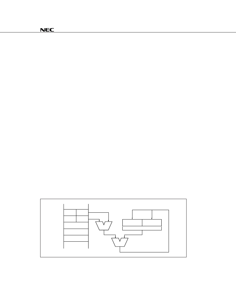
(a) MADD16 (Multiply and Add 16-bit Integer)
This instruction multiplies the contents of general-purpose register rs by the contents of general-purpose
register rt. Both the operands are treated as signed 16-bit integers. Bits 62 through 15 of both the
operands must be sign-extended.
The result of the multiplication is added to a 64-bit value combining special registers HI and LO. The
low-order word (64 bits) of the result is loaded to special register LO, and the high-order word is loaded
to HI.
An integer overflow exception does not occur.
Figure 3-3 outline the operation of the MADD16 instruction.
Figure 3-3. Operation of MADD16 Instruction
rs
rt
31
15
General-purpose register file
MUL
ADD
HI
LO
63
31
High-order
Low-order
相關(guān)PDF資料 |
PDF描述 |
|---|---|
| μPD30121 | 64-Bit MIPS RISC Microprocessor(64 位RISC 微處理器) |
| μPD30122 | 64-Bit RISC Microprosessor(64位RISC微處理器) |
| μPD30181 | 64-Bit RISC Microprosessor(64位RISC微處理器) |
| μPD30210 | 64-Bit MIPS RISC Microprocessor(64位MIPS RISC 微處理器) |
| μPD30200 | High-Performance, 64-Bit RISC Microprosessor(高性能64位RISC微處理器) |
相關(guān)代理商/技術(shù)參數(shù) |
參數(shù)描述 |
|---|---|
| PD301-024-03-PC | 制造商:未知廠家 制造商全稱:未知廠家 功能描述:Analog IC |
| PD301-024-03-P-C-200 | 制造商:未知廠家 制造商全稱:未知廠家 功能描述:DC to DC Converter |
| PD301-024-03-P-C-250 | 制造商:未知廠家 制造商全稱:未知廠家 功能描述:DC to DC Converter |
| PD301-024-03-P-C-300 | 制造商:未知廠家 制造商全稱:未知廠家 功能描述:DC to DC Converter |
| PD301-024-03-PI | 制造商:未知廠家 制造商全稱:未知廠家 功能描述:Analog IC |
發(fā)布緊急采購,3分鐘左右您將得到回復(fù)。