- 您現(xiàn)在的位置:買賣IC網(wǎng) > PDF目錄376461 > XRT72L73 (Exar Corporation) Ultraframer DS3/E3/DS2/E2/DS1/E1/DS0 PDF資料下載
參數(shù)資料
| 型號(hào): | XRT72L73 |
| 廠商: | Exar Corporation |
| 元件分類: | 通信及網(wǎng)絡(luò) |
| 英文描述: | Ultraframer DS3/E3/DS2/E2/DS1/E1/DS0 |
| 中文描述: | Ultraframer DS3/E3/DS2/E2/DS1/E1/DS0 |
| 文件頁數(shù): | 23/105頁 |
| 文件大?。?/td> | 1307K |
| 代理商: | XRT72L73 |
第1頁第2頁第3頁第4頁第5頁第6頁第7頁第8頁第9頁第10頁第11頁第12頁第13頁第14頁第15頁第16頁第17頁第18頁第19頁第20頁第21頁第22頁當(dāng)前第23頁第24頁第25頁第26頁第27頁第28頁第29頁第30頁第31頁第32頁第33頁第34頁第35頁第36頁第37頁第38頁第39頁第40頁第41頁第42頁第43頁第44頁第45頁第46頁第47頁第48頁第49頁第50頁第51頁第52頁第53頁第54頁第55頁第56頁第57頁第58頁第59頁第60頁第61頁第62頁第63頁第64頁第65頁第66頁第67頁第68頁第69頁第70頁第71頁第72頁第73頁第74頁第75頁第76頁第77頁第78頁第79頁第80頁第81頁第82頁第83頁第84頁第85頁第86頁第87頁第88頁第89頁第90頁第91頁第92頁第93頁第94頁第95頁第96頁第97頁第98頁第99頁第100頁第101頁第102頁第103頁第104頁第105頁
á
XRT72L73
THREE CHANNEL, DS3 ATM UNI/CLEAR-CHANNEL FRAMER
PRELIMINARY
REV. P1.0.1
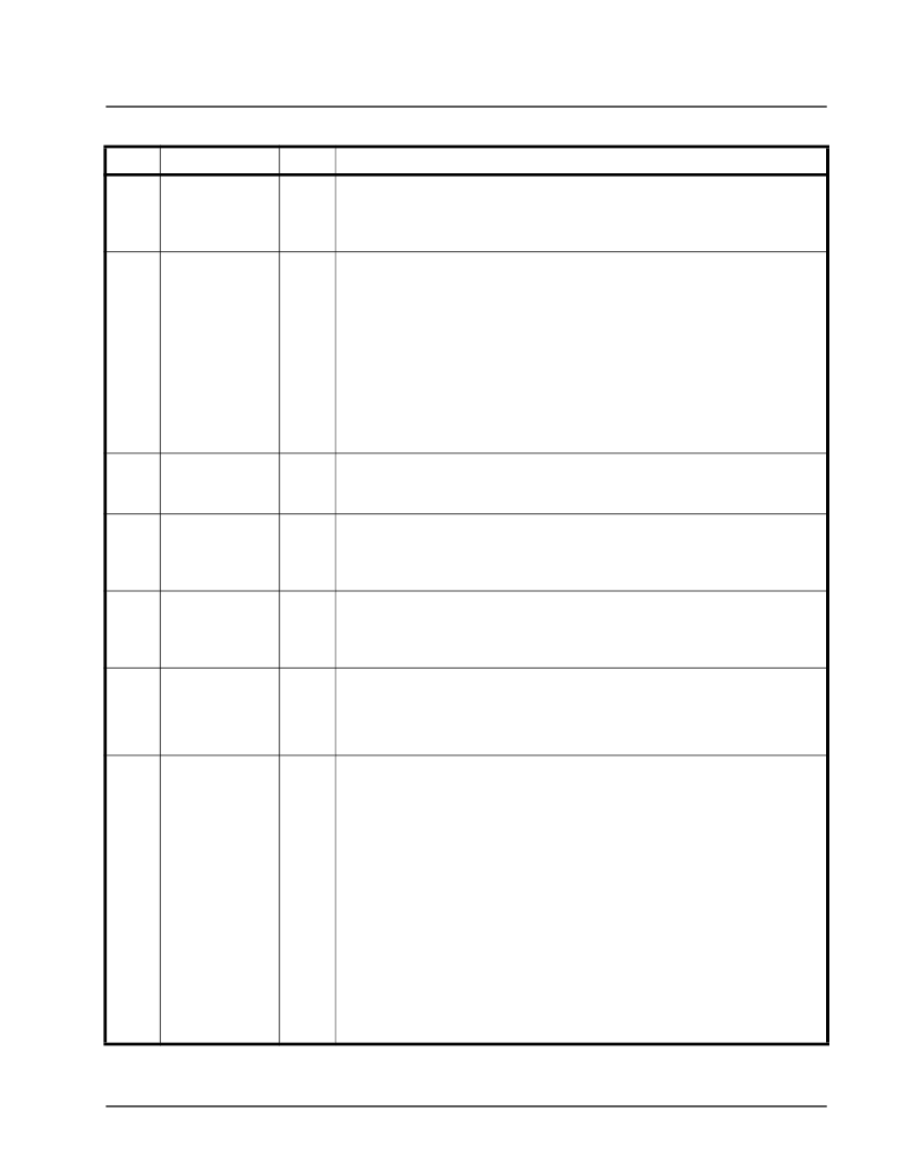
23
J25
J26
J23
RxLOS_0
RxLOS_1
RxLOS_2
O
Receive DS3 Framer—Loss of Signal Output Indicator:
This pin is asserted when the Receive DS3 Framer encounters 180 consecutive
0’s via the RxPOS and RxNEG pins. This pin will be negated once the Receive DS3
Framer has detected at least 60 “1s” out of 180 consecutive bits.
B4
C12
C17
RxNEG_0
RxNEG_1
RxNEG_2
I
Receive Negative Data Input:
The exact role of this input pin depends upon whether the UNI is operating in the
Unipolar or Bipolar Mode.
Unipolar Mode:
This input pin is inactive, and should be pulled (“Low” or "High") when the UNI is
operating in the Unipolar Mode.
Bipolar Mode:
This input pin functions as one of the dual rail inputs for the incoming AMI/B3ZS
encoded DS3 data that has been received from an external Line Interface Unit
(LIU) IC. RxPOS functions as the other dual rail input for the UNI. When this input
pin is asserted, it means that the LIU has received a “negative polarity” pulse from
the line.
B26
A25
B25
RxOH_0
RxOH_1
RxOH_2
O
Receive Overhead Output Port:
All overhead bits, which are received via the "Receive Section" of the Framer IC;
will be output via this output pin, upon the rising edge of RxOHClk.
B23
A23
C22
RxOHClk_0
RxOHClk_1
RxOHClk_2
O
Receive Overhead Output Clock Signal:
This pin serves as the clock signal for external device to sample the Overhead
data on the RxOH pin. The external interface should use the rising edge of this
clock to sample the OH data on RxOH pin.
D21
C20
B20
RxOHFrame_0
RxOHFrame_1
RxOHFrame_2
O
Receive Overhead Frame Boundary Indicator:
This pin is pulsed “High” for one RxOHClk period whenever the first 'X' bit is output
on RxOH pin. If external device samples this pin “High” on the rising edge of RxO-
HClk, the data on RxOH is 'X' bit (first OH bit in the received DS3 frame).
H25
H26
G24
RxOOF_0
RxOOF_1
RxOOF_2
O
Receiver DS3 Framer—“Out of Frame” Indicator:
The Receive DS3 Framerblock will assert this output signal (e.g., pull it “High”)
whenever it has declared an “Out of Frame” (OOF) condition with the incoming
DS3 frames. This signal is negated when the framer correctly locates the F- and
M-bits and regains synchronization with the DS3 frame.
R26
P24
P25
RxSerData/
RxPOH_0
RxSerData/
RxPOH_1
RxSerData/
RxPOH_2
O
Receive Serial Output/Receive PLCP Frame Path Overhead (POH) Byte
Serial Output Port—Output Pin:
The exact functionality of this output pin depends upon whether the XRT72L71
Framer IC is operating in the Clear Channel or ATM UNI Mode.
Clear Channel Mode:
In clear channel mode, all DS3 data which is received by XRT72L71 will be output
as a serial data stream via this pin. The XRT72L71 will output data (via this pin)
upon the falling edge of “RxSerClk”. As a consequence, this data should be sam-
pled with the rising edge of RxSerClk.
ATM UNI Mode:
This output pin, along with RxPOHClk, RxPOHFrame, and RxPOHIns pins com-
prise the “Receive PLCP Frame POH Byte” serial output port. For each PLCP
frame that is received by the Receive PLCP Processor, this serial output port will
output the contents of all 12 POH (Path Overhead) bytes. The data that is output
via this pin, is updated on the rising edge of the RxPOHClk output clock signal.
The RxPOHFrame pin will pulse “High” when the first bit of the Z6 byte is being
output on this output pin.
PIN DESCRIPTIONS
P
IN
#
N
AME
T
YPE
D
ESCRIPTION
相關(guān)PDF資料 |
PDF描述 |
|---|---|
| XRT72L74 | Ultraframer DS3/E3/DS2/E2/DS1/E1/DS0 |
| XRT7300IV | E3/DS3/STS-1 LINE INTERFACE UNIT |
| XRT7300 | E3/DS3/STS-1 LINE INTERFACE UNIT |
| XRT7302 | 2 Channel E3/DS3/STS-1 Line Interface Unit(2通道 E3/DS3/STS-1線接口單元) |
| XRT73L02M | TWO CHANNEL E3/DS3/STS-1 LINE INTERFACE UNIT |
相關(guān)代理商/技術(shù)參數(shù) |
參數(shù)描述 |
|---|---|
| XRT72L73IB | 制造商:未知廠家 制造商全稱:未知廠家 功能描述:Telecommunication IC |
| XRT72L74IB | 制造商:未知廠家 制造商全稱:未知廠家 功能描述:Telecommunication IC |
| XRT7300 | 制造商:EXAR 制造商全稱:EXAR 功能描述:E3/DS3/STS-1 LINE INTERFACE UNIT |
| XRT7300ES | 功能描述:網(wǎng)絡(luò)控制器與處理器 IC RoHS:否 制造商:Micrel 產(chǎn)品:Controller Area Network (CAN) 收發(fā)器數(shù)量: 數(shù)據(jù)速率: 電源電流(最大值):595 mA 最大工作溫度:+ 85 C 安裝風(fēng)格:SMD/SMT 封裝 / 箱體:PBGA-400 封裝:Tray |
| XRT7300IV | 功能描述:外圍驅(qū)動(dòng)器與原件 - PCI . . RoHS:否 制造商:PLX Technology 工作電源電壓: 最大工作溫度: 安裝風(fēng)格:SMD/SMT 封裝 / 箱體:FCBGA-1156 封裝:Tray |
發(fā)布緊急采購,3分鐘左右您將得到回復(fù)。