- 您現(xiàn)在的位置:買賣IC網(wǎng) > PDF目錄199479 > TSB43AA82PGE (TEXAS INSTRUMENTS INC) 2 CHANNEL(S), 400M bps, SERIAL COMM CONTROLLER, PQFP144 PDF資料下載
參數(shù)資料
| 型號(hào): | TSB43AA82PGE |
| 廠商: | TEXAS INSTRUMENTS INC |
| 元件分類: | 微控制器/微處理器 |
| 英文描述: | 2 CHANNEL(S), 400M bps, SERIAL COMM CONTROLLER, PQFP144 |
| 封裝: | PLASTIC, QFP-144 |
| 文件頁(yè)數(shù): | 140/146頁(yè) |
| 文件大小: | 770K |
| 代理商: | TSB43AA82PGE |
第1頁(yè)第2頁(yè)第3頁(yè)第4頁(yè)第5頁(yè)第6頁(yè)第7頁(yè)第8頁(yè)第9頁(yè)第10頁(yè)第11頁(yè)第12頁(yè)第13頁(yè)第14頁(yè)第15頁(yè)第16頁(yè)第17頁(yè)第18頁(yè)第19頁(yè)第20頁(yè)第21頁(yè)第22頁(yè)第23頁(yè)第24頁(yè)第25頁(yè)第26頁(yè)第27頁(yè)第28頁(yè)第29頁(yè)第30頁(yè)第31頁(yè)第32頁(yè)第33頁(yè)第34頁(yè)第35頁(yè)第36頁(yè)第37頁(yè)第38頁(yè)第39頁(yè)第40頁(yè)第41頁(yè)第42頁(yè)第43頁(yè)第44頁(yè)第45頁(yè)第46頁(yè)第47頁(yè)第48頁(yè)第49頁(yè)第50頁(yè)第51頁(yè)第52頁(yè)第53頁(yè)第54頁(yè)第55頁(yè)第56頁(yè)第57頁(yè)第58頁(yè)第59頁(yè)第60頁(yè)第61頁(yè)第62頁(yè)第63頁(yè)第64頁(yè)第65頁(yè)第66頁(yè)第67頁(yè)第68頁(yè)第69頁(yè)第70頁(yè)第71頁(yè)第72頁(yè)第73頁(yè)第74頁(yè)第75頁(yè)第76頁(yè)第77頁(yè)第78頁(yè)第79頁(yè)第80頁(yè)第81頁(yè)第82頁(yè)第83頁(yè)第84頁(yè)第85頁(yè)第86頁(yè)第87頁(yè)第88頁(yè)第89頁(yè)第90頁(yè)第91頁(yè)第92頁(yè)第93頁(yè)第94頁(yè)第95頁(yè)第96頁(yè)第97頁(yè)第98頁(yè)第99頁(yè)第100頁(yè)第101頁(yè)第102頁(yè)第103頁(yè)第104頁(yè)第105頁(yè)第106頁(yè)第107頁(yè)第108頁(yè)第109頁(yè)第110頁(yè)第111頁(yè)第112頁(yè)第113頁(yè)第114頁(yè)第115頁(yè)第116頁(yè)第117頁(yè)第118頁(yè)第119頁(yè)第120頁(yè)第121頁(yè)第122頁(yè)第123頁(yè)第124頁(yè)第125頁(yè)第126頁(yè)第127頁(yè)第128頁(yè)第129頁(yè)第130頁(yè)第131頁(yè)第132頁(yè)第133頁(yè)第134頁(yè)第135頁(yè)第136頁(yè)第137頁(yè)第138頁(yè)第139頁(yè)當(dāng)前第140頁(yè)第141頁(yè)第142頁(yè)第143頁(yè)第144頁(yè)第145頁(yè)第146頁(yè)
81
8 BD FIFOs (Total 1182 Quadlets)
The bulky data FIFOs consist of the DTF (data transmit FIFO) and the DRF (data receive FIFO). These FIFOs are
primarily used for large data transfers through the bulky interface, but can be accessed by the host.
8.1
Setting the BD FIFO Size
DTF:
Data transmit FIFO
adjustable
DRF:
Data receive/fetch FIFO
adjustable
8.1.1
DTF
If the auto header insertion mode (DTHdIs = 1 at 90h, bit 24) is selected, the packet payload is written into the DMA
data transmit FIFO (DTF). If this mode is not selected, transmission data including header is written to the DTF.
Considering this, set necessary packet quadlet size for DTF_Size on DTF/DRF size (98h).
After DMA finishes writing one packet of data, it starts a packet transmission request on 1394 bus. For efficiency, it
is recommended that DTF_Size be set to more than double the data size of one request packet. This enables
multiplex packet transmission time and transmission data writing time.
8.1.2
DRF
The complete packet, including the header and trailer of the response packet is written in the data response FIFO
(DRF). This is the same when the response header strip mode is used. Thus, DRF_Size (quadlet) in DTF/DRF size
(98h) needs to be larger than the response header and trailer.
8.2
DTF/DRF Packet Format
The data formats for the transmission and reception of data through the DMA bulky interface are shown in the
following sections. The transmit formats describe the expected organization of data presented to the TSB43AA82
at the DMA bulky interface. The receive formats describe the expected organization of data that the TSB43AA82
presents to the DMA bulky interface.
8.2.1
DRF Packet Format
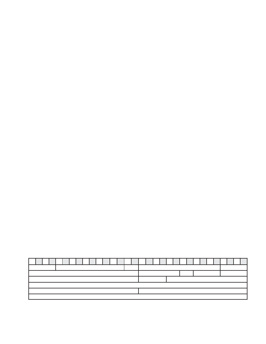
The DRF packet format shown in Figure 81 describes the data format of the packet received at the DMA bulky
interface. The first quadlet contains the status of the received packet. The first 16 bits of the second quadlet contain
the destination bus and node number, the remaining 16-bits contain packet-control information. The first 16 bits of
the second quadlet contain the bus and node number of the destination node, and the last 16 bits contain packet
control information. The first 16 bits of the third quadlet contain the bus and node number of the source node. The
first 16 bits of the fifth quadlet contain the length of the data and the last 16-bits contain the extended tCodes. All
remaining quadlets contain data that is used only for write requests and read responses. For block read requests and
block write responses, the data field is omitted. Table 8-1 shows a description of each field.
0
1
2
3
4
5
6
7
8
9
10 11
12 13
14 15
16 17
18 19 20 21 22 23 24 25 26 27 28 29 30 31
status
Reserved
spd
Reserved
ack
destination ID
tLabel
rt
tCode
prior
source ID
rCode
Reserved
data_length
extended_tCode
block data
Figure 81. DRF Block-Receive Packet Format
相關(guān)PDF資料 |
PDF描述 |
|---|---|
| TSB43AA82GGW | 2 CHANNEL(S), 400M bps, SERIAL COMM CONTROLLER, PBGA176 |
| TSB43DA42GHCR | PCI BUS CONTROLLER, PBGA196 |
| TSB500SK02 | 30 A, BARRIER STRIP TERMINAL BLOCK, 1 ROW, 1 DECK |
| TSB500SK10MDS | 30 A, BARRIER STRIP TERMINAL BLOCK, 1 ROW, 1 DECK |
| TSB5000331DS | 30 A, BARRIER STRIP TERMINAL BLOCK, 1 ROW, 1 DECK |
相關(guān)代理商/技術(shù)參數(shù) |
參數(shù)描述 |
|---|---|
| TSB43AA82PGEG4 | 功能描述:1394 接口集成電路 2Port Hi Per Int Phy & Link Layer Chip RoHS:否 制造商:Texas Instruments 類型:Link Layer Controller 工作電源電壓: 封裝 / 箱體:LQFP 封裝:Tray |
| TSB43AB21 | 制造商:TI 制造商全稱:Texas Instruments 功能描述:INTERGRATED 1394A-2000 OHCI PHY LINK-LAYER CONTROLLER |
| TSB43AB21A | 制造商:TI 制造商全稱:Texas Instruments 功能描述:Integrated 1394a-2000 OHCI PHY/Link-Layer Controller |
| TSB43AB21A-EP | 制造商:未知廠家 制造商全稱:未知廠家 功能描述:Military Enhanced Plastic Integrated 1394a-2000 OCHI pHY/Link-Layer Controller |
| TSB43AB21AI | 制造商:TI 制造商全稱:Texas Instruments 功能描述:Integrated 1394a-2000 OHCI PHY/Link-Layer Controller |
發(fā)布緊急采購(gòu),3分鐘左右您將得到回復(fù)。