- 您現(xiàn)在的位置:買賣IC網(wǎng) > PDF目錄369950 > PCI1620PDV Controller Miscellaneous - Datasheet Reference PDF資料下載
參數(shù)資料
| 型號(hào): | PCI1620PDV |
| 英文描述: | Controller Miscellaneous - Datasheet Reference |
| 中文描述: | 控制器雜項(xiàng)-數(shù)據(jù)表參考 |
| 文件頁(yè)數(shù): | 60/164頁(yè) |
| 文件大?。?/td> | 720K |
| 代理商: | PCI1620PDV |
第1頁(yè)第2頁(yè)第3頁(yè)第4頁(yè)第5頁(yè)第6頁(yè)第7頁(yè)第8頁(yè)第9頁(yè)第10頁(yè)第11頁(yè)第12頁(yè)第13頁(yè)第14頁(yè)第15頁(yè)第16頁(yè)第17頁(yè)第18頁(yè)第19頁(yè)第20頁(yè)第21頁(yè)第22頁(yè)第23頁(yè)第24頁(yè)第25頁(yè)第26頁(yè)第27頁(yè)第28頁(yè)第29頁(yè)第30頁(yè)第31頁(yè)第32頁(yè)第33頁(yè)第34頁(yè)第35頁(yè)第36頁(yè)第37頁(yè)第38頁(yè)第39頁(yè)第40頁(yè)第41頁(yè)第42頁(yè)第43頁(yè)第44頁(yè)第45頁(yè)第46頁(yè)第47頁(yè)第48頁(yè)第49頁(yè)第50頁(yè)第51頁(yè)第52頁(yè)第53頁(yè)第54頁(yè)第55頁(yè)第56頁(yè)第57頁(yè)第58頁(yè)第59頁(yè)當(dāng)前第60頁(yè)第61頁(yè)第62頁(yè)第63頁(yè)第64頁(yè)第65頁(yè)第66頁(yè)第67頁(yè)第68頁(yè)第69頁(yè)第70頁(yè)第71頁(yè)第72頁(yè)第73頁(yè)第74頁(yè)第75頁(yè)第76頁(yè)第77頁(yè)第78頁(yè)第79頁(yè)第80頁(yè)第81頁(yè)第82頁(yè)第83頁(yè)第84頁(yè)第85頁(yè)第86頁(yè)第87頁(yè)第88頁(yè)第89頁(yè)第90頁(yè)第91頁(yè)第92頁(yè)第93頁(yè)第94頁(yè)第95頁(yè)第96頁(yè)第97頁(yè)第98頁(yè)第99頁(yè)第100頁(yè)第101頁(yè)第102頁(yè)第103頁(yè)第104頁(yè)第105頁(yè)第106頁(yè)第107頁(yè)第108頁(yè)第109頁(yè)第110頁(yè)第111頁(yè)第112頁(yè)第113頁(yè)第114頁(yè)第115頁(yè)第116頁(yè)第117頁(yè)第118頁(yè)第119頁(yè)第120頁(yè)第121頁(yè)第122頁(yè)第123頁(yè)第124頁(yè)第125頁(yè)第126頁(yè)第127頁(yè)第128頁(yè)第129頁(yè)第130頁(yè)第131頁(yè)第132頁(yè)第133頁(yè)第134頁(yè)第135頁(yè)第136頁(yè)第137頁(yè)第138頁(yè)第139頁(yè)第140頁(yè)第141頁(yè)第142頁(yè)第143頁(yè)第144頁(yè)第145頁(yè)第146頁(yè)第147頁(yè)第148頁(yè)第149頁(yè)第150頁(yè)第151頁(yè)第152頁(yè)第153頁(yè)第154頁(yè)第155頁(yè)第156頁(yè)第157頁(yè)第158頁(yè)第159頁(yè)第160頁(yè)第161頁(yè)第162頁(yè)第163頁(yè)第164頁(yè)

3
–
18
Table 3
–
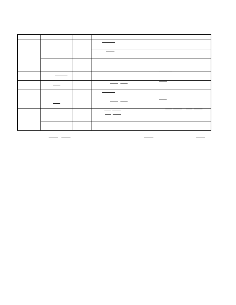
12. PC Card Interrupt Events and Description
CARD TYPE
EVENT
TYPE
SIGNAL
DESCRIPTION
Battery conditions
(BVD1, BVD2)
CSC
BVD1(STSCHG)//CSTSCHG
A transition on BVD1 indicates a change in the
PC Card battery conditions.
16-bit
memory
BVD2(SPKR)//CAUDIO
A transition on BVD2 indicates a change in the
PC Card battery conditions.
Wait states
(READY)
CSC
READY(IREQ)//CINT
A transition on READY indicates a change in the
ability of the memory PC Card to accept or provide
data.
16-bit I/O
Change in card
status (STSCHG)
CSC
BVD1(STSCHG)//CSTSCHG
The assertion of STSCHG indicates a status change
on the PC Card.
16-bit I/O/
UltraMedia
Interrupt request
(IREQ)
Functional
READY(IREQ)//CINT
The assertion of IREQ indicates an interrupt request
from the PC Card.
CardBus
Change in card
status (CSTSCHG)
CSC
BVD1(STSCHG)//CSTSCHG
The assertion of CSTSCHG indicates a status
change on the PC Card.
Interrupt request
(CINT)
Functional
READY(IREQ)//CINT
The assertion of CINT indicates an interrupt request
from the PC Card.
All PC Cards/
Smart Card
adapters/
ada ters/
UltraMedia/
Flash Media
Card insertion
or removal
CSC
CD1//CCD1,
CD2//CCD2
A transition on either CD1//CCD1 or CD2//CCD2
indicates an insertion or removal of a 16-bit or
CardBus PC Card.
Power cycle
complete
CSC
N/A
An interrupt is generated when a PC Card power-up
cycle has completed.
The naming convention for PC Card signals describes the function for 16-bit memory, I/O cards, and CardBus. For
example, READY(IREQ)//CINT includes READY for 16-bit memory cards, IREQ for 16-bit I/O cards, and CINT for
CardBus cards. The 16-bit memory card signal name is first, with the I/O card signal name second, enclosed in
parentheses. The CardBus signal name follows after a double slash (//).
The
1997 PC Card Standard
describes the power-up sequence that must be followed by the PCI1620 when an
insertion event occurs and the host requests that the socket V
CC
and V
PP
be powered. Upon completion of this
power-up sequence, the PCI1620 interrupt scheme can be used to notify the host system (see Table 3
–
12), denoted
by the power cycle complete event. This interrupt source is considered a PCI1620 internal event, because it depends
on the completion of applying power to the socket rather than on a signal change at the PC Card interface.
3.6.2
Interrupt Masks and Flags
Host software may individually mask (or disable) most of the potential interrupt sources listed in Table 3
–
12 by setting
the appropriate bits in the PCI1620. By individually masking the interrupt sources listed, software can control those
events that cause a PCI1620 interrupt. Host software has some control over the system interrupt the PCI1620 asserts
by programming the appropriate routing registers. The PCI1620 allows host software to route PC Card CSC and PC
Card functional interrupts to separate system interrupts. Interrupt routing somewhat specific to the interrupt signaling
method used is discussed in more detail in the following sections.
When an interrupt is signaled by the PCI1620, the interrupt service routine must determine which of the events listed
in Table 3
–
11 caused the interrupt. Internal registers in the PCI1620 provide flags that report the source of an interrupt.
By reading these status bits, the interrupt service routine can determine the action to be taken.
Table 3
–
11 details the registers and bits associated with masking and reporting potential interrupts. All interrupts can
be masked except the functional PC Card interrupts, and an interrupt status flag is available for all types of interrupts.
Notice that there is not a mask bit to stop the PCI1620 from passing PC Card functional interrupts through to the
appropriate interrupt scheme. These interrupts are not valid until the card is properly powered, and there should never
be a card interrupt that does not require service after proper initialization.
Table 3
–
11 lists the various methods of clearing the interrupt flag bits. The flag bits in the ExCA registers (16-bit PC
Card-related interrupt flags) can be cleared using two different methods. One method is an explicit write of 1 to the
flag bit to clear and the other is by reading the flag bit register. The selection of flag bit clearing methods is made by
相關(guān)PDF資料 |
PDF描述 |
|---|---|
| PCI2050A | 32-Bit. 66MHz. 9-Master PCI-to-PCI Bridge |
| PCI2050GHK | BUS CONTROLLER |
| PCI2050PDV | BUS CONTROLLER |
| PCI9054AB50BI | Interface IC |
| PCI9036 | Telecommunication IC |
相關(guān)代理商/技術(shù)參數(shù) |
參數(shù)描述 |
|---|---|
| PCI-1620U | 制造商:ADVANTECH 制造商全稱:Advantech Co., Ltd. 功能描述:8-port RS-232 PCI Communication Card, with Surge Protection |
| PCI1620ZHK | 功能描述:外圍驅(qū)動(dòng)器與原件 - PCI PC Card Flash & Smart Card Cntrlr RoHS:否 制造商:PLX Technology 工作電源電壓: 最大工作溫度: 安裝風(fēng)格:SMD/SMT 封裝 / 箱體:FCBGA-1156 封裝:Tray |
| PCI-1622A-BE | 制造商:Advantech Co Ltd 功能描述:8PORT RS-422/485 PCI COM CARD - Trays 制造商:Advantech Co Ltd 功能描述:8-port RS-422/485 UPCI COMM card |
| PCI-1622CU | 制造商:ADVANTECH 制造商全稱:Advantech Co., Ltd. 功能描述:8-port RS-422/485 Universal PCI Communication Card with Isolation & EFT Protection |
| PCI-1625U | 制造商:ADVANTECH 制造商全稱:Advantech Co., Ltd. 功能描述:8-port Intelligent RS-232 Universal PCI Communication Card |
發(fā)布緊急采購(gòu),3分鐘左右您將得到回復(fù)。