- 您現(xiàn)在的位置:買賣IC網(wǎng) > PDF目錄369950 > PCI1520-EP Military Enhanced Plastic PC Card Controllers Data Manual PDF資料下載
參數(shù)資料
| 型號: | PCI1520-EP |
| 英文描述: | Military Enhanced Plastic PC Card Controllers Data Manual |
| 中文描述: | 軍事增強(qiáng)塑料PC卡控制器數(shù)據(jù)手冊 |
| 文件頁數(shù): | 30/125頁 |
| 文件大?。?/td> | 716K |
| 代理商: | PCI1520-EP |
第1頁第2頁第3頁第4頁第5頁第6頁第7頁第8頁第9頁第10頁第11頁第12頁第13頁第14頁第15頁第16頁第17頁第18頁第19頁第20頁第21頁第22頁第23頁第24頁第25頁第26頁第27頁第28頁第29頁當(dāng)前第30頁第31頁第32頁第33頁第34頁第35頁第36頁第37頁第38頁第39頁第40頁第41頁第42頁第43頁第44頁第45頁第46頁第47頁第48頁第49頁第50頁第51頁第52頁第53頁第54頁第55頁第56頁第57頁第58頁第59頁第60頁第61頁第62頁第63頁第64頁第65頁第66頁第67頁第68頁第69頁第70頁第71頁第72頁第73頁第74頁第75頁第76頁第77頁第78頁第79頁第80頁第81頁第82頁第83頁第84頁第85頁第86頁第87頁第88頁第89頁第90頁第91頁第92頁第93頁第94頁第95頁第96頁第97頁第98頁第99頁第100頁第101頁第102頁第103頁第104頁第105頁第106頁第107頁第108頁第109頁第110頁第111頁第112頁第113頁第114頁第115頁第116頁第117頁第118頁第119頁第120頁第121頁第122頁第123頁第124頁第125頁

3
–
2
The power-down sequence is:
1.
Assert GRST to the device to disable the outputs during power down. Output drivers must be powered down
in the high-impedance state to prevent high current levels through the clamp diodes to the 5-V clamping
rails (V
CCA
, V
CCB
, and V
CCP
).
Remove the clamp voltage.
2.
3.
Remove the 3.3-V power from V
CC
.
NOTE:
The clamp voltage can be ramped up or ramped down along with the 3.3-V power. The
voltage difference between V
CC
and the clamp voltage must remain within 3.6 V.
3.2
I/O Characteristics
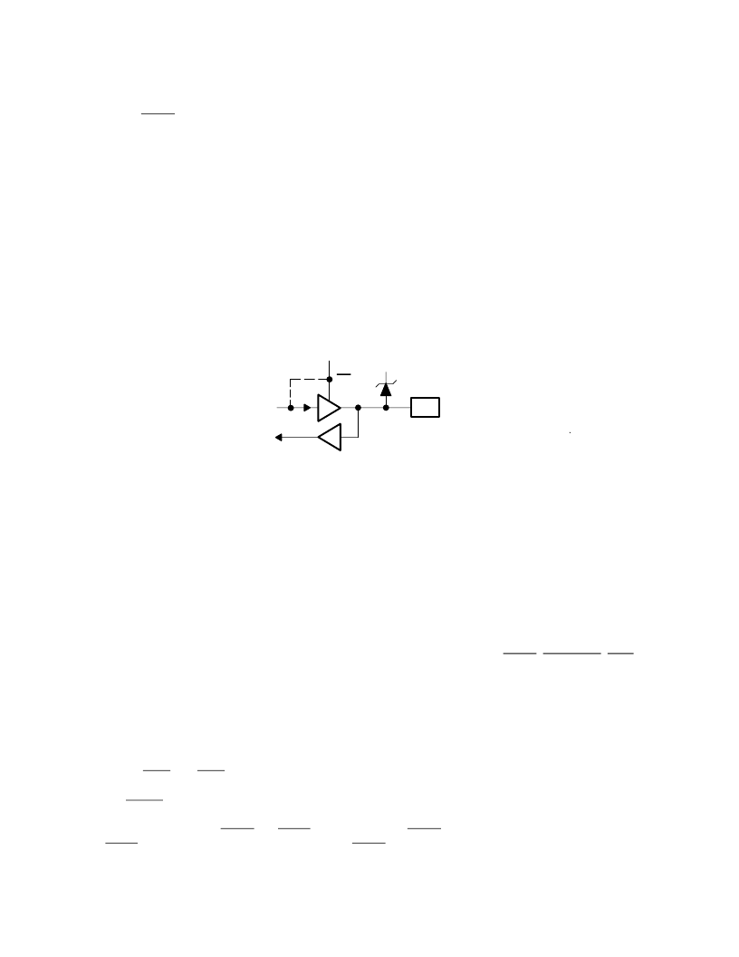
Figure 3
–
2 shows a 3-state bidirectional buffer. Section 7.2,
Recommended Operating Conditions
, provides the
electrical characteristics of the inputs and outputs.
NOTE:
The PCI1520 meets the ac specifications of the
1997 PC Card Standard
and
PCI Local
Bus Specification.
Tied for Open Drain
OE
Pad
VCCP
Figure 3
–
2. 3-State Bidirectional Buffer
NOTE:
Unused terminals (input or I/O) must be held high or low to prevent them from floating.
3.3
Clamping Voltages
The clamping voltages are set to match whatever external environment the PCI1520 is interfaced with, 3.3 V or 5 V.
The I/O sites can be pulled through a clamping diode to a voltage rail that protects the core from external signals.
The core power supply is always 3.3 V and is independent of the clamping voltages. For example, PCI signaling can
be either 3.3 V or 5 V, and the PCI1520 must reliably accommodate both voltage levels. This is accomplished by using
a 3.3-V I/O buffer that is 5-V tolerant, with the applicable clamping voltage applied. If a system designer desires a
5-V PCI bus, then V
CCP
can be connected to a 5-V power supply.
The PCI1520 requires three separate clamping voltages because it supports a wide range of features. The three
voltages are listed and defined in Section 7.2,
Recommended Operating Conditions
. GRST, SUSPEND, PME, and
CSTSCHG are not clamped to any of them.
3.4
Peripheral Component Interconnect (PCI) Interface
The PCI1520 is fully compliant with the
PCI Local Bus Specification
. The PCI1520 provides all required signals for
PCI master or slave operation, and may operate in either a 5-V or 3.3-V signaling environment by connecting the V
CCP
terminal to the desired voltage level. In addition to the mandatory PCI signals, the PCI1520 provides the optional
interrupt signals INTA and INTB.
3.4.1
PCI GRST Signal
During the power-up sequence, GRST and PRST must be asserted. GRST can only be deasserted 100
μ
s after PCLK
is stable. PRST can be deasserted at the same time as GRST or any time thereafter.
相關(guān)PDF資料 |
PDF描述 |
|---|---|
| PCI1620GHK | Controller Miscellaneous - Datasheet Reference |
| PCI1620PDV | Controller Miscellaneous - Datasheet Reference |
| PCI2050A | 32-Bit. 66MHz. 9-Master PCI-to-PCI Bridge |
| PCI2050GHK | BUS CONTROLLER |
| PCI2050PDV | BUS CONTROLLER |
相關(guān)代理商/技術(shù)參數(shù) |
參數(shù)描述 |
|---|---|
| PCI1520GHK | 功能描述:外圍驅(qū)動器與原件 - PCI PC CARD CONTROLLER RoHS:否 制造商:PLX Technology 工作電源電壓: 最大工作溫度: 安裝風(fēng)格:SMD/SMT 封裝 / 箱體:FCBGA-1156 封裝:Tray |
| PCI1520I | 制造商:TI 制造商全稱:Texas Instruments 功能描述:PC CARD CONTROLLERS |
| PCI1520IGHK | 功能描述:外圍驅(qū)動器與原件 - PCI PC CARD CONTROLLER RoHS:否 制造商:PLX Technology 工作電源電壓: 最大工作溫度: 安裝風(fēng)格:SMD/SMT 封裝 / 箱體:FCBGA-1156 封裝:Tray |
| PCI1520IGHKEP | 功能描述:外圍驅(qū)動器與原件 - PCI Mil Enhance PC Card Cntrlr Data Manual RoHS:否 制造商:PLX Technology 工作電源電壓: 最大工作溫度: 安裝風(fēng)格:SMD/SMT 封裝 / 箱體:FCBGA-1156 封裝:Tray |
| PCI1520IPDV | 功能描述:外圍驅(qū)動器與原件 - PCI PC CARD CONTROLLER RoHS:否 制造商:PLX Technology 工作電源電壓: 最大工作溫度: 安裝風(fēng)格:SMD/SMT 封裝 / 箱體:FCBGA-1156 封裝:Tray |
發(fā)布緊急采購,3分鐘左右您將得到回復(fù)。