- 您現在的位置:買賣IC網 > PDF目錄377495 > intel M80C186 (Intel Corp.) CHMOS High Integration 16-Bit Microprocessor(CHMOS 高集成16位微處理器) PDF資料下載
參數資料
| 型號: | intel M80C186 |
| 廠商: | Intel Corp. |
| 英文描述: | CHMOS High Integration 16-Bit Microprocessor(CHMOS 高集成16位微處理器) |
| 中文描述: | CHMOS高集成的16位微處理器(CHMOS高集成16位微處理器) |
| 文件頁數: | 37/59頁 |
| 文件大?。?/td> | 529K |
| 代理商: | INTEL M80C186 |
第1頁第2頁第3頁第4頁第5頁第6頁第7頁第8頁第9頁第10頁第11頁第12頁第13頁第14頁第15頁第16頁第17頁第18頁第19頁第20頁第21頁第22頁第23頁第24頁第25頁第26頁第27頁第28頁第29頁第30頁第31頁第32頁第33頁第34頁第35頁第36頁當前第37頁第38頁第39頁第40頁第41頁第42頁第43頁第44頁第45頁第46頁第47頁第48頁第49頁第50頁第51頁第52頁第53頁第54頁第55頁第56頁第57頁第58頁第59頁
M80C186
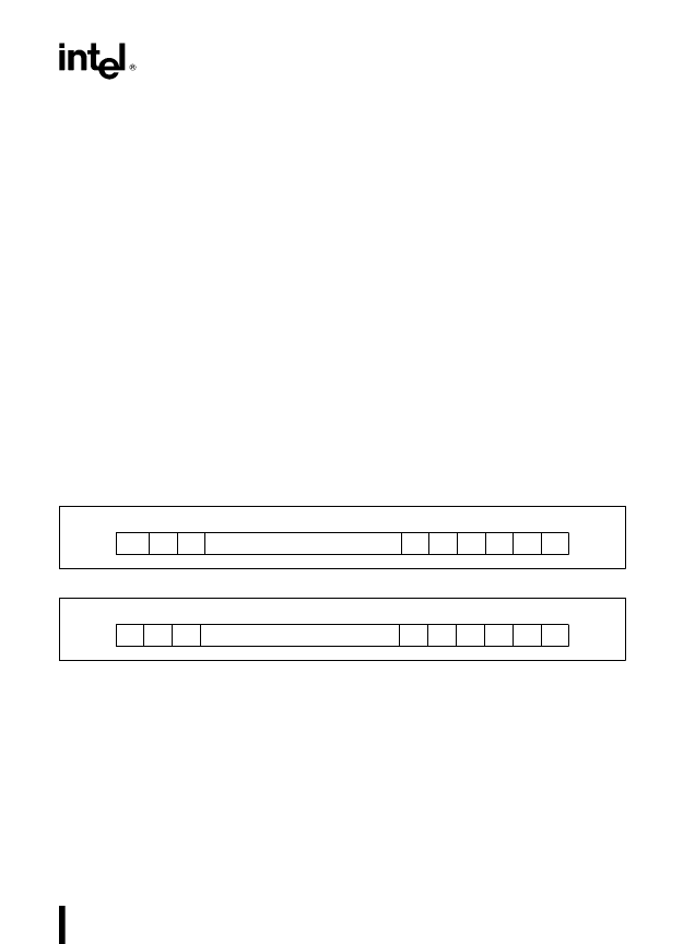
Poll and Poll Status Registers
These registers contain polling information. The for-
mat of these registers is shown in Figure 32. They
can only be read. Reading the Poll register consti-
tutes a software poll. This will set the IS bit of the
highest priority pending interrupt. Reading the poll
status register will not set the IS bit of the highest
priority pending interrupt; only the status of pending
interrupts will be provided.
Encoding of the Poll and Poll Status register bits are
as follows:
S
x
:
Encoded information that indicates the
vector type of the highest priority inter-
rupting source. Valid only when INTREQ
e
1.
INTREQ: This bit determines if an interrupt request
is present. Interrupt Request
e
1; no In-
terrupt Request
e
0.
SLAVE MODE OPERATION
When slave mode is used, the internal M80C186 in-
terrupt controller will be used as a slave controller to
an external master interrupt controller. The internal
M80C186 resources will be monitored by the internal
interrupt controller, while the external controller
functions as the system master interrupt controller.
Upon reset, the M80C186 will be in master mode. To
provide for slave mode operation bit 14 of the relo-
cation register should be set.
Because of pin limitations caused by the need to
interface to an external M82C59A master, the inter-
nal interrupt controller will no longer accept external
inputs. There are however, enough M80C186 inter-
rupt controller inputs (internally) to dedicate one to
each timer. In this mode, each timer interrupt source
has its own mask bit, IS bit, and control word.
In slave mode each peripheral must be assigned a
unique priority to ensure proper interrupt controller
operation. Therefore, it is the programmer’s respon-
sibility to assign correct priorities and initialize inter-
rupt control registers before enabling interrupts.
Slave Mode External Interface
The configuration of the M80C186 with respect to an
external M82C59A master is shown in Figure 33.
The INT0 (Pin 45) input is used as the M80C186
CPU interrupt input. INT3 (Pin 41) functions as an
output to send the M80C186 slave-interrupt-request
to one of the 8 master-PIC-inputs.
15
14
13
5
4
3
2
1
0
SPEC/
NSPEC
0
0
#
#
#
#
#
#
#
0
S4
S3
S2
S1
S0
Figure 31. EOI Register Format
15
INT
REQ
14
13
5
4
3
2
1
0
0
0
#
#
#
#
#
#
#
0
S4
S3
S2
S1
S0
Figure 32. Poll and Poll Status Register Format
37
相關PDF資料 |
PDF描述 |
|---|---|
| intel Pentium CPU | 32 Bit CPU With MMX Technology and Mobile Module(32位帶MMX和移動模塊處理器) |
| intel Pentium II processor | Pentium II Processor Mobile Module(帶移動模塊奔II處理器) |
| INTEL386 CXSA | 5-V 32-Bit Fully Static Embedded Microprocessor(5V,32位完全靜態(tài)嵌入式微處理器) |
| INTEL386 CXSB | Low-Voltage, 32-Bit, Fully Static Embedded Microprocessor(低電壓32位完全靜態(tài)嵌入式微處理器) |
| intel386 DX | 32-Bit CHMOS Microprocessor With Integrated Memory Management(32位CHMOS 微處理器帶集成存儲管理) |
相關代理商/技術參數 |
參數描述 |
|---|---|
| INTEN I/O PCB | 制造商:Sliger Designs, Inc. 功能描述:I/O PCB - Bulk |
| INTEN LED PCB | 制造商:Sliger Designs, Inc. 功能描述:LED PCB - Bulk |
| INTEN-1-PROTO | 制造商:Sliger Designs, Inc. 功能描述:QUANTITY TWO PROTO TYPE SHEET METAL - Bulk |
| INTENSI-FI | 制造商:BOARDCOM 制造商全稱:Broadcom Corporation. 功能描述:DRAFT-802.11n PRODUCT FAMILY |
| INTER0.5 | 制造商:POWERDATA TECHNOLOGIES 功能描述:LEAD WIELAND TO WIELAND 0.5M |
發(fā)布緊急采購,3分鐘左右您將得到回復。