- 您現(xiàn)在的位置:買賣IC網(wǎng) > PDF目錄67684 > IBM25PPC970MP7TR21AFT 64-BIT, 1600 MHz, RISC PROCESSOR, CBGA575 PDF資料下載
參數(shù)資料
| 型號(hào): | IBM25PPC970MP7TR21AFT |
| 元件分類: | 微控制器/微處理器 |
| 英文描述: | 64-BIT, 1600 MHz, RISC PROCESSOR, CBGA575 |
| 封裝: | 25 X 25 MM, 1 MM PITCH, CERAMIC, BGA-575 |
| 文件頁數(shù): | 65/74頁 |
| 文件大?。?/td> | 845K |
| 代理商: | IBM25PPC970MP7TR21AFT |
第1頁第2頁第3頁第4頁第5頁第6頁第7頁第8頁第9頁第10頁第11頁第12頁第13頁第14頁第15頁第16頁第17頁第18頁第19頁第20頁第21頁第22頁第23頁第24頁第25頁第26頁第27頁第28頁第29頁第30頁第31頁第32頁第33頁第34頁第35頁第36頁第37頁第38頁第39頁第40頁第41頁第42頁第43頁第44頁第45頁第46頁第47頁第48頁第49頁第50頁第51頁第52頁第53頁第54頁第55頁第56頁第57頁第58頁第59頁第60頁第61頁第62頁第63頁第64頁當(dāng)前第65頁第66頁第67頁第68頁第69頁第70頁第71頁第72頁第73頁第74頁
Datasheet
PowerPC 970MP RISC Microprocessor
System Design Information
Page 68 of 74
Version 1.3
January 17, 2008
PLL_MULT
1
In
Selects PLL multiplication factor:
0
Multiply reference frequency by 12.
1
Multiply reference frequency by 8.
PLL_RANGE(1:0)
2
In
To select the PLL frequency range, see Table 5-2 PowerPC
—
PLLTEST
1
In
For manufacturing test use only.
—
PLLTESTOUT
1
Out
Measure the PLL output (divided by 64).
—
PROCID(0:1)
2
In
System: processor ID
—
PSRO_ENABLE
1
In
For manufacturing test use only.
—
CP0_PSRO0
1
Out
For manufacturing test use only.
—
PSYNC
1
In
System: phase synchronization with companion chip
—
PULSE_SEL(0:2)
3
In
—
CP0_QACK
1In
System: acknowledgment of quiescence from the system for
core 0.
—
CP1_QACK
1In
System: acknowledgment of quiescence from the system for
core 1.
—
CP0_QREQ
1Out
System: request from processor to quiesce the system (nap
mode).
CP1_QREQ
1Out
System: request from processor to quiesce the system (nap
mode).
RI
1
In
For manufacturing test use only.
—
SPARE1
1
In/Out
SPARE2
1
In/Out
CP0_SRESET
1
In
System: soft reset for core 0.
—
CP1_SRESET
1
In
System: soft reset for core 1.
—
SRIN(0:1)
2
In
System: PI snoop response in.
—
SRIN(0:1)
2
In
System: PI inverse of snoop response in.
—
SROUT(0:1)
2
Out
System: PI snoop response out.
—
SROUT(0:1)
2
Out
System: PI inverse of snoop response out.
—
SYNC_ENABLE
1
In
For manufacturing test use only.
—
SYSCLK
1
In
System reference clock (differential input).
—
SYSCLK
1
In
System reference clock (differential input).
—
TBEN
1
In
System: time base enable
—
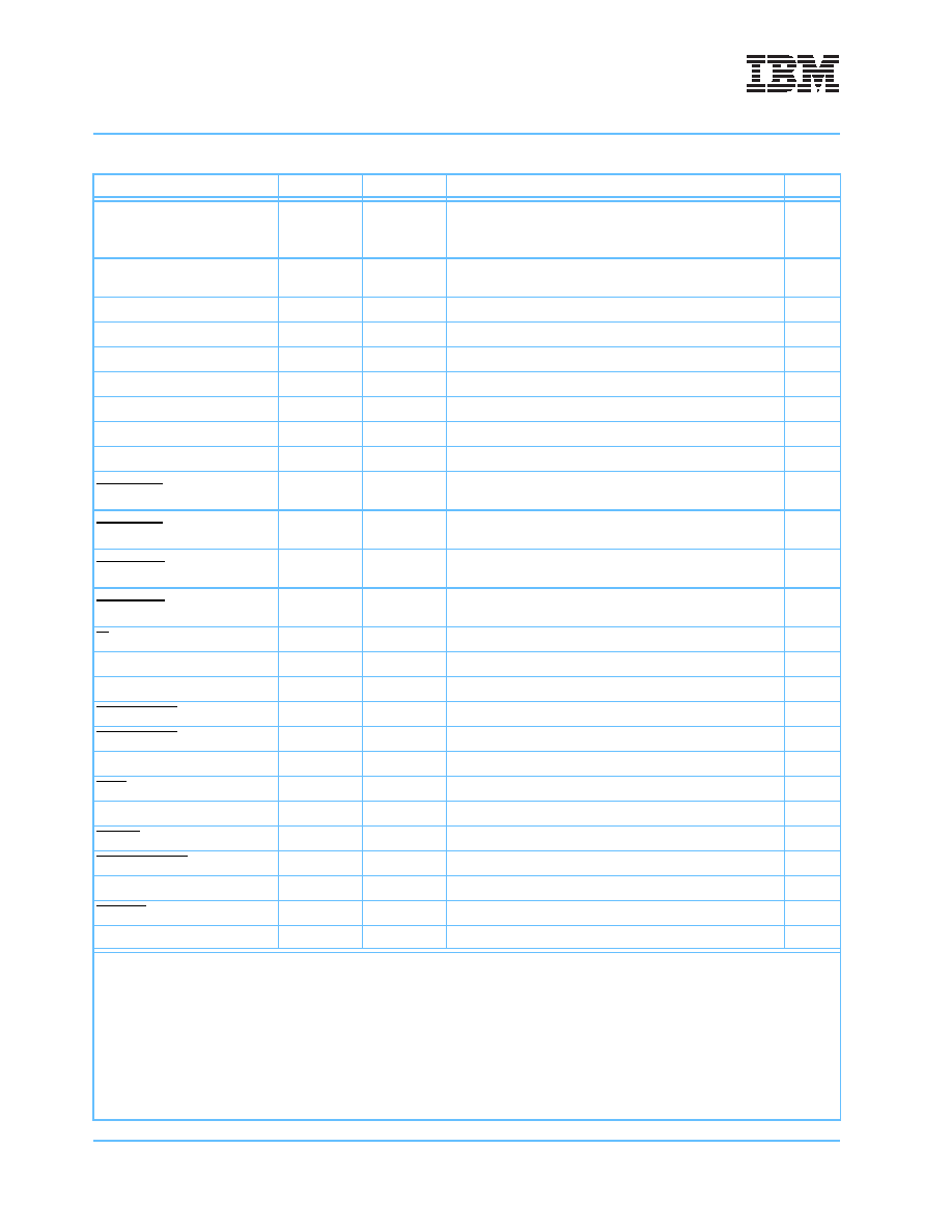
Table 5-9. Input/Output Signal Descriptions (Page 3 of 4)
Pin Name
Width
In/Out
System/Debug Function
Notes
Notes:
1. Bus ratios 8:1 and 24:1 are not supported for processor input (PI) functionality.
2. Using the 4:1 or 12:1 ratio with a multiplier of 12 limits the use of power tuning to (frequency)/2.
3. The PLL_MULT can be overwritten by JTAG commands. See the PowerPC 970MP RISC Microprocessor Design Guide or the Pow-
erPC 970MP User’s Manual for more details.
4. OD = open drain. BiDi = bidirectional.
5. For a PowerPC 970MP, MASTERSEL must be controlled by the service processor to easily read the fuse string for each core. The
fuse string is not to be read during normal operation. During normal operation of a PowerPC 970MP, MASTERSEL must always be
set to low (including during the entire power-up sequence)
6. See Table 5-8 PowerPC 970MP Pins for Manufacturing Test Only on page 65.
相關(guān)PDF資料 |
PDF描述 |
|---|---|
| IBM26BL486DX2-V66QP | 32-BIT, 66 MHz, MICROPROCESSOR, PQFP208 |
| IBM26BL486DX2-V80QP | 32-BIT, 80 MHz, MICROPROCESSOR, PQFP208 |
| IBM26BL486DX2-V50GP | 32-BIT, 50 MHz, MICROPROCESSOR, CPGA168 |
| IBM26BL486DX2-V50QP | 32-BIT, 50 MHz, MICROPROCESSOR, PQFP208 |
| IBM26BL486DX2-66GP | 32-BIT, 66 MHz, MICROPROCESSOR, CPGA168 |
相關(guān)代理商/技術(shù)參數(shù) |
參數(shù)描述 |
|---|---|
| IBM25PPC970MP7TR23AET | 制造商:IBM 功能描述:ANTARES MP DD1.1X 1.8GHZ PERFORMANCE OPTIMIZED - Trays |
| IBM25PPC970MP7TR30AET | 制造商:IBM Microelectronics 功能描述:ANTARES MP DD1.1X 2.0GHZ PERFORMANCE OPTIMIZED - Trays |
| IBM25PPC970MP7TR40AET | 制造商:IBM 功能描述:ANTARES MP DD1.1X 2.5GHZ PERFORMANCE OPTIMIZED - Trays |
| IBM25PPC970MP7TR50AET | 制造商:IBM 功能描述:ANTARES MP DD1.1X 1.2GHZ POWER OPTIMIZED - Trays |
| IBM25PPC970MP7TR60AET | 制造商:IBM 功能描述:ANTARES MP DD1.1X 1.4GHZ POWER OPTIMIZED - Trays |
發(fā)布緊急采購,3分鐘左右您將得到回復(fù)。