- 您現(xiàn)在的位置:買賣IC網(wǎng) > PDF目錄67684 > IBM25PPC970MP7TR21AFT 64-BIT, 1600 MHz, RISC PROCESSOR, CBGA575 PDF資料下載
參數(shù)資料
| 型號: | IBM25PPC970MP7TR21AFT |
| 元件分類: | 微控制器/微處理器 |
| 英文描述: | 64-BIT, 1600 MHz, RISC PROCESSOR, CBGA575 |
| 封裝: | 25 X 25 MM, 1 MM PITCH, CERAMIC, BGA-575 |
| 文件頁數(shù): | 61/74頁 |
| 文件大小: | 845K |
| 代理商: | IBM25PPC970MP7TR21AFT |
第1頁第2頁第3頁第4頁第5頁第6頁第7頁第8頁第9頁第10頁第11頁第12頁第13頁第14頁第15頁第16頁第17頁第18頁第19頁第20頁第21頁第22頁第23頁第24頁第25頁第26頁第27頁第28頁第29頁第30頁第31頁第32頁第33頁第34頁第35頁第36頁第37頁第38頁第39頁第40頁第41頁第42頁第43頁第44頁第45頁第46頁第47頁第48頁第49頁第50頁第51頁第52頁第53頁第54頁第55頁第56頁第57頁第58頁第59頁第60頁當前第61頁第62頁第63頁第64頁第65頁第66頁第67頁第68頁第69頁第70頁第71頁第72頁第73頁第74頁
Datasheet
PowerPC 970MP RISC Microprocessor
System Design Information
Page 64 of 74
Version 1.3
January 17, 2008
5.6 Pullup and Pulldown Recommendations
For reliable operation, it is highly recommended that the unused inputs be connected to an appropriate
signal level. For example:
Unused active-low inputs should be pulled up to OVDD.
Multiple unused active-high inputs can be ganged together for convenience.
Unused active-high inputs should be connected to GND.
Multiple unused active-low inputs can be ganged together for convenience.
All no-connect (NC) signals must remain unconnected.
Power and ground connections must be made to all external V0, V1, OVDD, AVDD, ANALOG_GND, and GND
pins of the PowerPC 970MP.
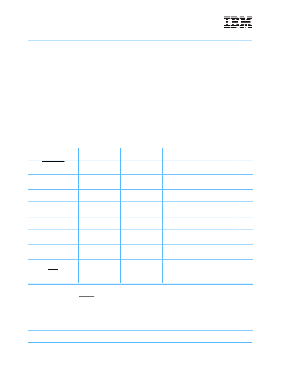
Table 5-7 provides details about the pin settings and information of the PowerPC 970MP debug and bringup
signals. Table 5-8 on page 65 provides details about the appropriate connections for the PowerPC 970MP
manufacturing-test-only signals.
Table 5-7. PowerPC 970MP Debug and Bringup Pin Settings and Information
Pin Name
In/Out/BiDi/JTAG1
Pull-up and Pull-Down
Resistor Setting2
Comments
Notes
AVP_RESET
In
Up
C1_UND_GLOBAL
In
Down
C2_UND_GLOBAL
In
Down
GPULDBG
In
Up
I2CGO
OD
Up
Semaphore providing arbitration between
I2C and JTAG.
I2CSEL
In
—
Allows external selection of the I2C or
JTAG interface for controlling scan func-
tionality.
TCK
In-JTAG
Up
JTAG – test clock
TDI
In-JTAG
Up
JTAG – test data in
TDO
Out-JTAG
Up
JTAG – test data out
TMS
In-JTAG
Up
JTAG – test mode select
TRIGGEROUT
Out
Down
Make visible to external hardware.
TRST
In-JTAG
Up
Only needed for debug. HRESET performs
the common on-chip processor (COP)
reset function. Should be wired to the
debug connector. Pulled up to OVDD by a
10 k
Ω resistor.
1. BiDi = Bidirectional.
2. Pullups should use a 10 k
Ω resistor to OV
DD. Pulldowns should use a 10 kΩ resistor to GND.
3. If GPULDBG = ‘1’ during HRESET transition from low to high, then run power-on reset (POR) in debug mode and stop after each
POR instruction.
If GPULDBG = ‘0’ during HRESET transition from low to high, then run POR without stopping after each POR instruction.
Toggling GPULDBG from ‘1’ to ‘0’ later on will exit the POR debug mode and continue without stopping after each instruction. See
the PowerPC 970MP Power-On Reset Application Note. for more information.
5. Pull-up and pull-down settings are application dependent. See Section 3.10.3 I2C and JTAG Considerations on page 43.
相關PDF資料 |
PDF描述 |
|---|---|
| IBM26BL486DX2-V66QP | 32-BIT, 66 MHz, MICROPROCESSOR, PQFP208 |
| IBM26BL486DX2-V80QP | 32-BIT, 80 MHz, MICROPROCESSOR, PQFP208 |
| IBM26BL486DX2-V50GP | 32-BIT, 50 MHz, MICROPROCESSOR, CPGA168 |
| IBM26BL486DX2-V50QP | 32-BIT, 50 MHz, MICROPROCESSOR, PQFP208 |
| IBM26BL486DX2-66GP | 32-BIT, 66 MHz, MICROPROCESSOR, CPGA168 |
相關代理商/技術參數(shù) |
參數(shù)描述 |
|---|---|
| IBM25PPC970MP7TR23AET | 制造商:IBM 功能描述:ANTARES MP DD1.1X 1.8GHZ PERFORMANCE OPTIMIZED - Trays |
| IBM25PPC970MP7TR30AET | 制造商:IBM Microelectronics 功能描述:ANTARES MP DD1.1X 2.0GHZ PERFORMANCE OPTIMIZED - Trays |
| IBM25PPC970MP7TR40AET | 制造商:IBM 功能描述:ANTARES MP DD1.1X 2.5GHZ PERFORMANCE OPTIMIZED - Trays |
| IBM25PPC970MP7TR50AET | 制造商:IBM 功能描述:ANTARES MP DD1.1X 1.2GHZ POWER OPTIMIZED - Trays |
| IBM25PPC970MP7TR60AET | 制造商:IBM 功能描述:ANTARES MP DD1.1X 1.4GHZ POWER OPTIMIZED - Trays |
發(fā)布緊急采購,3分鐘左右您將得到回復。