- 您現(xiàn)在的位置:買賣IC網(wǎng) > PDF目錄373427 > SMJ34020AHT (Texas Instruments, Inc.) GRAPHICS SYSTEM PROCESSOR PDF資料下載
參數(shù)資料
| 型號: | SMJ34020AHT |
| 廠商: | Texas Instruments, Inc. |
| 英文描述: | GRAPHICS SYSTEM PROCESSOR |
| 中文描述: | 圖形系統(tǒng)處理器 |
| 文件頁數(shù): | 71/92頁 |
| 文件大?。?/td> | 1458K |
| 代理商: | SMJ34020AHT |
第1頁第2頁第3頁第4頁第5頁第6頁第7頁第8頁第9頁第10頁第11頁第12頁第13頁第14頁第15頁第16頁第17頁第18頁第19頁第20頁第21頁第22頁第23頁第24頁第25頁第26頁第27頁第28頁第29頁第30頁第31頁第32頁第33頁第34頁第35頁第36頁第37頁第38頁第39頁第40頁第41頁第42頁第43頁第44頁第45頁第46頁第47頁第48頁第49頁第50頁第51頁第52頁第53頁第54頁第55頁第56頁第57頁第58頁第59頁第60頁第61頁第62頁第63頁第64頁第65頁第66頁第67頁第68頁第69頁第70頁當前第71頁第72頁第73頁第74頁第75頁第76頁第77頁第78頁第79頁第80頁第81頁第82頁第83頁第84頁第85頁第86頁第87頁第88頁第89頁第90頁第91頁第92頁
SMJ34020A
GRAPHICS SYSTEMPROCESSOR
SGUS011B – APRIL 1991 – REVISED AUGUST 1995
71
POST OFFICE BOX 1443
HOUSTON, TEXAS 77251–1443
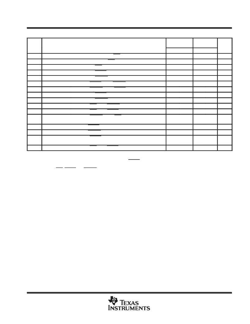
host-interface-cycle timing requirements (see Note 6 and Figure 36)
’34020-32
’34020A-32
’34020A-40
NO.
MIN
MAX
MIN
MAX
UNIT
23
tsu(AV-CSL)
th(CSL-AV)
tw(CSH)
tw(RDH)
tw(WRH)
tsu(RDH-WRL)
tsu(WRH-RDL)
tw(RDL)
tw(WRL)
tsu(CSL-WRH)
tsu(RDL-CK2L)
Setup time, address prior to HCS no longer high
12
10
ns
24
Hold time, address after HCS low
12
10
ns
25
Pulse duration, HCS high
28
25
ns
26
Pulse duration, HREAD high
28
25
ns
27
Pulse duration, HWRITE high
28
25
ns
28
Setup time, HREAD high to HWRITE no longer high
28
25
ns
29
Setup time, HWRITE high to HREAD no longer high
28
25
ns
30
Pulse duration, HREAD low
18
15
ns
31
Pulse duration, HWRITE low
18
15
ns
32
Setup time, HCS low to HWRITE no longer low
18
30
15
25
ns
33
Setup time, HCS low or HREAD low to LCLK2 no longer high
ns
34
tsu(WRH-CK2L)
Setup time, HWRITE high or HCS high to LCLK2 no longer
high
30
25
ns
35
th(CK2L-RDH)
th(CK2L-WRL)
Hold time, HREAD high after LCLK2 no longer high
0
0
0
0
ns
36
Hold time, HWRITE low after LCLK2 no longer high
ns
37
tsu(RDH-CK2L)
Setup time, HREAD high to LCLK2 no longer high, prefetch
read mode
30§
25§
ns
38
tsu(CSL-RDH)
Setup time, HCS low to HREAD no longer low
18
15
ns
Setup time to ensure recognition of input on this clock edge.
Hold time required to assure response on next clock edge. These values are based on computer simulation and are not tested.
§When the SMJ34020A is set for block reads, use the deassertion of HREAD to request a local memory cycle at the next sequential address
location.
NOTE 6: Although HCS, HREAD, and HWRITE can be totally asynchronous to the SMJ34020A, cycle responses to the signals are determined
by local memory cycles.
相關PDF資料 |
PDF描述 |
|---|---|
| SMJ4256 | 262,144-BIT DYNAMIC RANDOM-ACCESS MEMORY |
| SMJ4256FV | 262,144-BIT DYNAMIC RANDOM-ACCESS MEMORY |
| SMJ4256JD | 262,144-BIT DYNAMIC RANDOM-ACCESS MEMORY |
| SMJ44400 | 1M x 4 DRAM DYNAMIC RANDOM-ACCESS MEMORY |
| SMJ44400HR | 1M x 4 DRAM DYNAMIC RANDOM-ACCESS MEMORY |
相關代理商/技術參數(shù) |
參數(shù)描述 |
|---|---|
| SMJ34020AHTM32 | 制造商:TI 制造商全稱:Texas Instruments 功能描述:GRAPHICS SYSTEM PROCESSOR |
| SMJ34020AHTM40 | 制造商:TI 制造商全稱:Texas Instruments 功能描述:GRAPHICS SYSTEM PROCESSOR |
| SMJ34020HTM28 | 制造商:Rochester Electronics LLC 功能描述:- Bulk 制造商:Texas Instruments 功能描述: |
| SMJ34061GB | 制造商:未知廠家 制造商全稱:未知廠家 功能描述:Non-VGA Video Controller |
| SMJ34061GBS | 制造商:Rochester Electronics LLC 功能描述:- Bulk |
發(fā)布緊急采購,3分鐘左右您將得到回復。