- 您現(xiàn)在的位置:買賣IC網(wǎng) > PDF目錄67968 > MC68HLC705KJ1CDW (MOTOROLA INC) 8-BIT, OTPROM, 4 MHz, MICROCONTROLLER, PDSO16 PDF資料下載
參數(shù)資料
| 型號(hào): | MC68HLC705KJ1CDW |
| 廠商: | MOTOROLA INC |
| 元件分類: | 微控制器/微處理器 |
| 英文描述: | 8-BIT, OTPROM, 4 MHz, MICROCONTROLLER, PDSO16 |
| 封裝: | SOIC-16 |
| 文件頁數(shù): | 51/117頁 |
| 文件大小: | 1644K |
| 代理商: | MC68HLC705KJ1CDW |
第1頁第2頁第3頁第4頁第5頁第6頁第7頁第8頁第9頁第10頁第11頁第12頁第13頁第14頁第15頁第16頁第17頁第18頁第19頁第20頁第21頁第22頁第23頁第24頁第25頁第26頁第27頁第28頁第29頁第30頁第31頁第32頁第33頁第34頁第35頁第36頁第37頁第38頁第39頁第40頁第41頁第42頁第43頁第44頁第45頁第46頁第47頁第48頁第49頁第50頁當(dāng)前第51頁第52頁第53頁第54頁第55頁第56頁第57頁第58頁第59頁第60頁第61頁第62頁第63頁第64頁第65頁第66頁第67頁第68頁第69頁第70頁第71頁第72頁第73頁第74頁第75頁第76頁第77頁第78頁第79頁第80頁第81頁第82頁第83頁第84頁第85頁第86頁第87頁第88頁第89頁第90頁第91頁第92頁第93頁第94頁第95頁第96頁第97頁第98頁第99頁第100頁第101頁第102頁第103頁第104頁第105頁第106頁第107頁第108頁第109頁第110頁第111頁第112頁第113頁第114頁第115頁第116頁第117頁
Central Processor Unit (CPU)
CPU Registers
MC68HC705KJ1MC68HRC705KJ1MC68HLC705KJ1 — Rev. 4.0
Data Sheet
MOTOROLA
Central Processor Unit (CPU)
39
4.5.5 Condition Code Register
The condition code register is an 8-bit register whose three most significant bits are
permanently fixed at 111. The condition code register contains the interrupt mask
and four flags that indicate the results of the instruction just executed.
H — Half-Carry Flag
The CPU sets the half-carry flag when a carry occurs between bits 3 and 4 of
the accumulator during an ADD or ADC operation. The half-carry flag is required
for binary-coded decimal (BCD) arithmetic operations.
I — Interrupt Mask
Setting the interrupt mask disables interrupts. If an interrupt request occurs
while the interrupt mask is logic 0, the CPU saves the CPU registers on the
stack, sets the interrupt mask, and then fetches the interrupt vector. If an
interrupt request occurs while the interrupt mask is logic 1, the interrupt request
is latched. Normally, the CPU processes the latched interrupt request as soon
as the interrupt mask is cleared again.
A return from interrupt instruction (RTI) unstacks the CPU registers, restoring
the interrupt mask to its cleared state. After any reset, the interrupt mask is set
and can be cleared only by a software instruction.
N — Negative Flag
The CPU sets the negative flag when an ALU operation produces a negative
result.
Z — Zero Flag
The CPU sets the zero flag when an ALU operation produces a result of $00.
C — Carry/Borrow Flag
The CPU sets the carry/borrow flag when an addition operation produces a
carry out of bit 7 of the accumulator or when a subtraction operation requires a
borrow. Some logical operations and data manipulation instructions also clear
or set the carry/borrow flag.
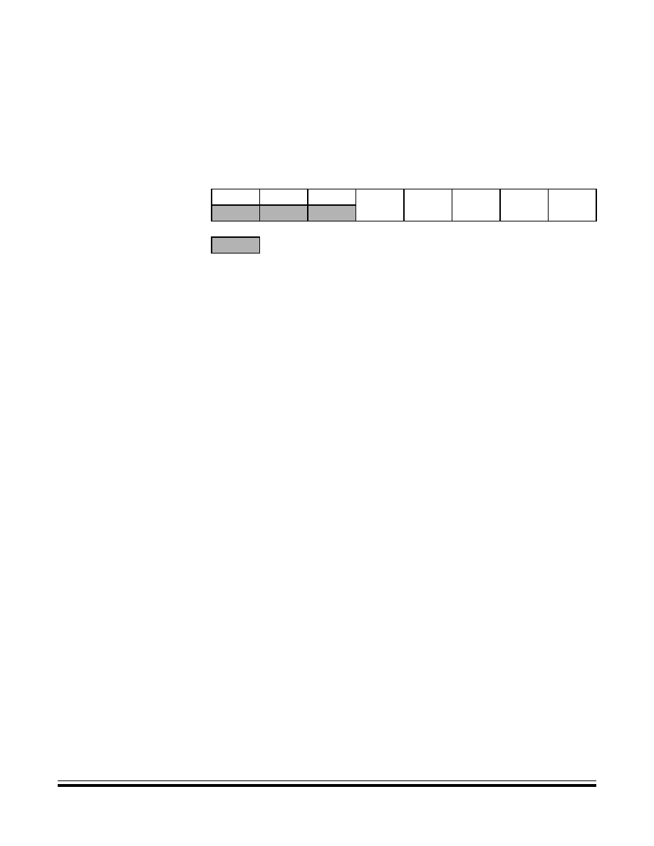
Bit 7
654321
Bit 0
Read:
1
HIN
Z
C
Write:
Reset:
111
U
1
U
= Unimplemented
U = Unaffected
Figure 4-6. Condition Code Register (CCR)
相關(guān)PDF資料 |
PDF描述 |
|---|---|
| MC68HC705KJ1CP | 8-BIT, OTPROM, 4 MHz, MICROCONTROLLER, PDIP16 |
| MC68HLC705KJ1CP | 8-BIT, OTPROM, 4 MHz, MICROCONTROLLER, PDIP16 |
| MC7455ARX867LG | 32-BIT, 867 MHz, RISC PROCESSOR, CBGA483 |
| MC7445ARX733LG | 32-BIT, 733 MHz, RISC PROCESSOR, CBGA360 |
| MC7445ARX1000LG | 32-BIT, 1000 MHz, RISC PROCESSOR, CBGA360 |
相關(guān)代理商/技術(shù)參數(shù) |
參數(shù)描述 |
|---|---|
| MC68HLC908JK3CP | 制造商:Rochester Electronics LLC 功能描述:- Bulk |
| MC68HLC908QT1CFQ | 制造商:Rochester Electronics LLC 功能描述:- Bulk |
| MC68HLC908QT4CDW | 制造商:Rochester Electronics LLC 功能描述:- Bulk |
| MC68HLC908QT4CFQ | 制造商:Rochester Electronics LLC 功能描述:- Bulk |
| MC68HLC908QY1CDW | 制造商:Rochester Electronics LLC 功能描述:LOW V-1.5K FLASH W/O ADC - Bulk |
發(fā)布緊急采購,3分鐘左右您將得到回復(fù)。