- 您現(xiàn)在的位置:買賣IC網(wǎng) > PDF目錄98007 > M44C510-P40 (ATMEL CORP) 4-BIT, MROM, MICROCONTROLLER, PDIP40 PDF資料下載
參數(shù)資料
| 型號: | M44C510-P40 |
| 廠商: | ATMEL CORP |
| 元件分類: | 微控制器/微處理器 |
| 英文描述: | 4-BIT, MROM, MICROCONTROLLER, PDIP40 |
| 封裝: | DIP-40 |
| 文件頁數(shù): | 56/57頁 |
| 文件大小: | 1105K |
| 代理商: | M44C510-P40 |
第1頁第2頁第3頁第4頁第5頁第6頁第7頁第8頁第9頁第10頁第11頁第12頁第13頁第14頁第15頁第16頁第17頁第18頁第19頁第20頁第21頁第22頁第23頁第24頁第25頁第26頁第27頁第28頁第29頁第30頁第31頁第32頁第33頁第34頁第35頁第36頁第37頁第38頁第39頁第40頁第41頁第42頁第43頁第44頁第45頁第46頁第47頁第48頁第49頁第50頁第51頁第52頁第53頁第54頁第55頁當(dāng)前第56頁第57頁
M44C510
TELEFUNKEN Semiconductors
Rev. A2, 13-Jan-98
8 (57)
1.2.4
ALU
TOS–1
CCR
RAM
TOS–2
SP
TOS–3
TOS
ALU
TOS–4
94 8977
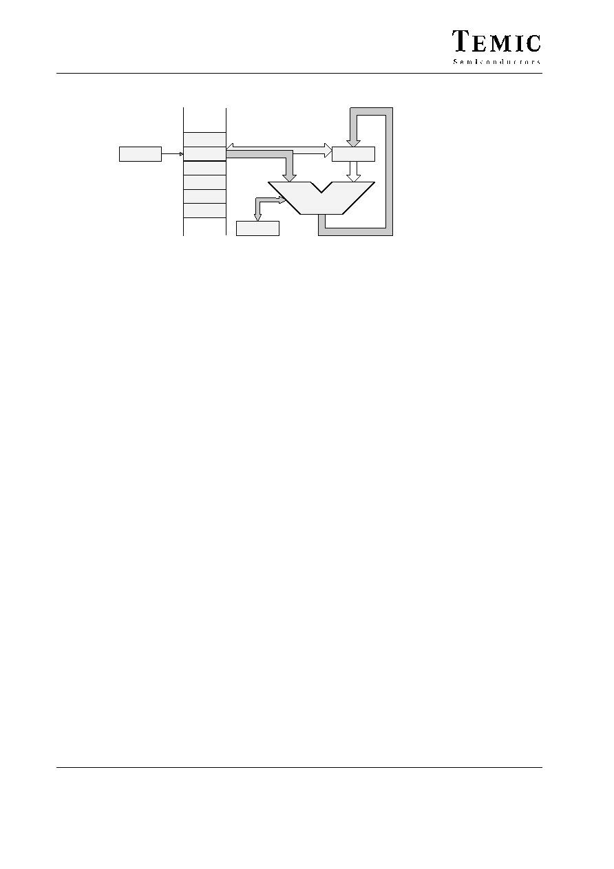
Figure 7. ALU zero-address operations
The 4-bit ALU performs all the arithmetical, logical, shift
and rotate operations with the top two elements of the ex-
pression stack (TOS and TOS-1) and returns the result to
the TOS. The ALU operations affect the carry/borrow and
branch flag in the condition code register (CCR).
1.2.5
Instruction Set
The MARC4 instruction set is optimized for the high-
level programming language qFORTH. Many MARC4
instructions are qFORTH words. This enables the com-
piler to generate a fast and compact program code. The
CPU has an instruction pipeline which allows the control-
ler to prefetch an instruction from ROM at the same time
as the present instruction is being executed. The MARC4
is a zero-address machine. The instructions contain only
the operation to be performed and no source or destination
address fields. The operations are implicitly performed
on the data placed on the stack. There are one and two
byte instructions which are executed within 1 to 4
machine cycles. A MARC4 machine cycle is made up of
two system clock (SYSCL) cycles. Most of the instruc-
tions are only one byte long and are executed in a single
machine cycle.
1.2.6
I/O Bus
The I/O ports and the registers of the peripheral modules
(Timer 0, Timer 1, Interval timer, Watchdog etc.) are I/O
mapped. All communication between the core and the on-
chip peripherals takes place via the I/O bus and the
associated I/O control. With the MARC4 IN and OUT
instructions, the I/O bus enables a direct read or write
access to one of the 16 primary I/O addresses. More about
the I/O access to the on-chip peripherals is described in
the “Peripheral Modules”. The I/O bus is internal and is
not accessible by the customer on the final micro-
controller device, but is used as the interface for the
MARC4 emulation (see also the section “Emulation”).
1.3
Interrupt Structure
The MARC4 can handle interrupts with eight different
priority levels. They can be generated from the internal
and external interrupt sources or by a software interrupt
from the CPU itself. Each interrupt level has a hard-wired
priority and an associated vector for the service routine in
the ROM (see table 2, page 10). The programmer can
postpone the processing of interrupts by resetting the in-
terrupt enable flag (I) in the CCR. An interrupt occurrence
will still be registered but the interrupt routine is only
started after the I flag is set. All interrupts can be masked,
and the priority individually software configured by pro-
gramming the appropriate control register of the
interrupting module (see section “Peripheral Modules”).
相關(guān)PDF資料 |
PDF描述 |
|---|---|
| M44C510D-XXX-DOW | 4-BIT, MROM, MICROCONTROLLER |
| M44C588 | 4-BIT, MROM, 4 MHz, MICROCONTROLLER |
| M44C892 | 4-BIT, MROM, 4 MHz, MICROCONTROLLER, PDSO20 |
| M48T08Y-15PC1 | 0 TIMER(S), REAL TIME CLOCK, PDMA28 |
| M48T08Y-10PC1 | 0 TIMER(S), REAL TIME CLOCK, PDMA28 |
相關(guān)代理商/技術(shù)參數(shù) |
參數(shù)描述 |
|---|---|
| M44C890 | 制造商:ATMEL 制造商全稱:ATMEL Corporation 功能描述:Low-Current Microcontroller for Wireless Communication |
| M44C890-H | 制造商:ATMEL 制造商全稱:ATMEL Corporation 功能描述:Low-Current Microcontroller for Wireless Communication |
| M44S05K4F1 | 功能描述:汽車連接器 MX44 Terminals RoHS:否 制造商:Amphenol SINE Systems 產(chǎn)品:Contacts 系列:ATP 位置數(shù)量: 型式:Female 安裝風(fēng)格: 端接類型: 觸點(diǎn)電鍍:Nickel |
| M44T332538880MHZ | 制造商:MEC 功能描述: |
| M44T3338880MHZ | 制造商:MEC 功能描述: |
發(fā)布緊急采購,3分鐘左右您將得到回復(fù)。