- 您現(xiàn)在的位置:買賣IC網(wǎng) > PDF目錄379184 > DS80CH11 System Energy Manager PDF資料下載
參數(shù)資料
| 型號: | DS80CH11 |
| 英文描述: | System Energy Manager |
| 中文描述: | 系統(tǒng)能量管理器 |
| 文件頁數(shù): | 54/88頁 |
| 文件大小: | 598K |
| 代理商: | DS80CH11 |
第1頁第2頁第3頁第4頁第5頁第6頁第7頁第8頁第9頁第10頁第11頁第12頁第13頁第14頁第15頁第16頁第17頁第18頁第19頁第20頁第21頁第22頁第23頁第24頁第25頁第26頁第27頁第28頁第29頁第30頁第31頁第32頁第33頁第34頁第35頁第36頁第37頁第38頁第39頁第40頁第41頁第42頁第43頁第44頁第45頁第46頁第47頁第48頁第49頁第50頁第51頁第52頁第53頁當前第54頁第55頁第56頁第57頁第58頁第59頁第60頁第61頁第62頁第63頁第64頁第65頁第66頁第67頁第68頁第69頁第70頁第71頁第72頁第73頁第74頁第75頁第76頁第77頁第78頁第79頁第80頁第81頁第82頁第83頁第84頁第85頁第86頁第87頁第88頁
DS80CH11
011200 54/88
When an AMQ bit is set to 1, the corresponding activity
monitor input pin is qualified with IOR or IOW. As a
result, the corresponding AMF bit will not be set unless
the programmed state on the AMI.n pin is accompanied
with a valid IOR or IOW signal. This prevents false trig-
gering of activity monitor inputs from chip select outputs
due to address decoding glitches.
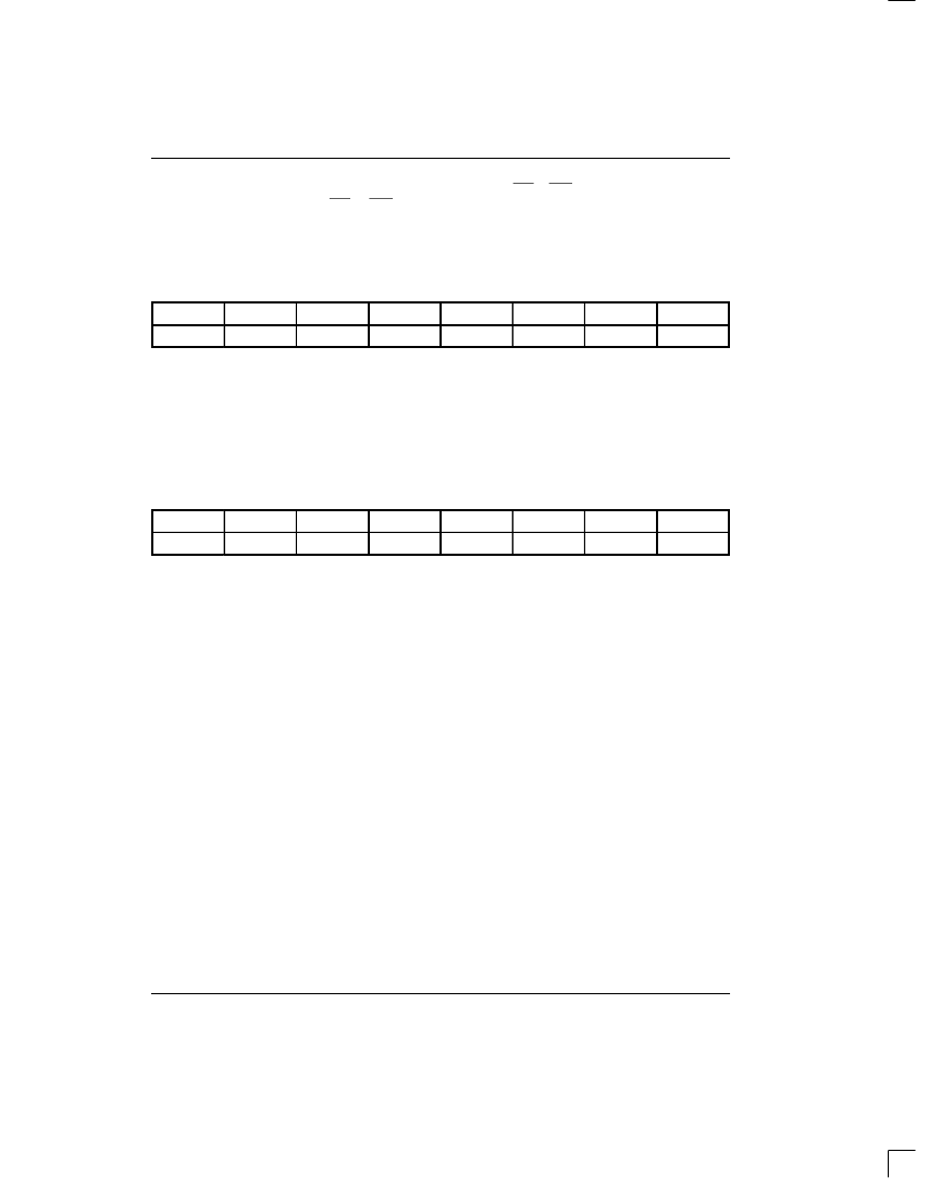
8.5
AMP – ACTIVITY MONITOR POLARITY REGISTER
AMP; SFR ADDR.=094H
BIT 7
BIT 6
BIT 5
BIT 4
BIT 3
BIT 2
BIT 1
BIT 0
AMP7
AMP6
AMP5
AMP4
AMP3
AMP2
AMP1
AMP0
Read/Write Access: Unrestricted.
Initialization: 00h on any type of reset
The bits in the AMP register are used to select the polar-
ity of a valid state on the activity monitor input pins.
When an AMP bit is set to 1, a high state is selected as
valid on the corresponding AMI pin. When and AMP bit
= 0, a low state is selected as valid.
8.6
AMF – ACTIVITY MONITOR FLAG REGISTER
AMF; SFR ADDR.=095H
BIT 7
BIT 6
BIT 5
BIT 4
BIT 3
BIT 2
BIT 1
BIT 0
AMF7
AMF6
AMF5
AMF4
AMF3
AMF2
AMF1
AMF0
Read/Write Access: Unrestricted.
Initialization: 00h on any type of reset
An AMF bit will be set whenever a valid state is detected
on the associated AMI.n pin. A valid state is determined
by the programming of the Activity Monitor Polarity reg-
ister and the Activity Monitor Qualifier register, both
described above. If the associated AME bit is set, the
AMF bit is enabled as an interrupt source. An SEM inter-
rupt will be recognized if the EAM is also set, enabling
activity monitor interrupts. Upon receiving an activity
monitor interrupt, the system should read the AMF reg-
ister to determine the source of interrupt. An AMF bit
can be cleared by writing it to a 0 to clear the interrupt
source condition. Writing a 1 has no effect.
8.7
Part 7 can also be used to control LED’s by turning them
on or off. To turn on an LED, the Port 7.X bit must be pro-
grammed to a logic 0 allowing current to sink into the
DS80CH11. To turn off an LED the Port 7.X but must be
programmed to a logic 1, preventing any current flow
LED CONTROL
through the LED circuit. Each Port 7 pin is capable of
sinking 10mA of current. When using this port for LED
control it is recommended that no more than 40mA of
sink current be dissipated at a time into the DS80CH11.
相關PDF資料 |
PDF描述 |
|---|---|
| DS83C520 | EPROM/ROM High-Speed Micro |
| DS83C520-ECL | EPROM/ROM High-Speed Micro |
| DS83C520-ENL | EPROM/ROM High-Speed Micro |
| DS83C520-MCL | EPROM/ROM High-Speed Micro |
| DS83C520-MNL | EPROM/ROM High-Speed Micro |
相關代理商/技術參數(shù) |
參數(shù)描述 |
|---|---|
| DS80CH11+E02 | 制造商:Maxim from Components Direct 功能描述:MAXIM DS80CH11+E02 SYSTEM ENERGY MANAGERS - Trays 制造商:Maxim 功能描述:Maxim DS80CH11+E02 System Energy Managers |
| DS80CH11-E02 | 制造商:Maxim from Components Direct 功能描述:MAXIM DS80CH11-E02 SYSTEM ENERGY MANAGERS - Trays 制造商:Maxim 功能描述:Maxim DS80CH11-E02 System Energy Managers |
| DS80E100 | 制造商:NSC 制造商全稱:National Semiconductor 功能描述:5 to 12.5 Gbps, Power-Saver Equalizer for Backplanes and Cables |
| DS80EP100 | 制造商:NSC 制造商全稱:National Semiconductor 功能描述:5 to 12.5 Gbps, Power-Saver Equalizer for Backplanes and Cables |
| DS80EP100_08 | 制造商:NSC 制造商全稱:National Semiconductor 功能描述:5 to 12.5 Gbps, Power-Saver Equalizer for Backplanes and Cables |
發(fā)布緊急采購,3分鐘左右您將得到回復。