- 您現(xiàn)在的位置:買賣IC網(wǎng) > PDF目錄69028 > MCC68HC711D3 (MOTOROLA INC) 8-BIT, OTPROM, 3 MHz, MICROCONTROLLER, UUC PDF資料下載
參數(shù)資料
| 型號(hào): | MCC68HC711D3 |
| 廠商: | MOTOROLA INC |
| 元件分類: | 微控制器/微處理器 |
| 英文描述: | 8-BIT, OTPROM, 3 MHz, MICROCONTROLLER, UUC |
| 封裝: | DIE |
| 文件頁(yè)數(shù): | 18/157頁(yè) |
| 文件大小: | 2252K |
| 代理商: | MCC68HC711D3 |
第1頁(yè)第2頁(yè)第3頁(yè)第4頁(yè)第5頁(yè)第6頁(yè)第7頁(yè)第8頁(yè)第9頁(yè)第10頁(yè)第11頁(yè)第12頁(yè)第13頁(yè)第14頁(yè)第15頁(yè)第16頁(yè)第17頁(yè)當(dāng)前第18頁(yè)第19頁(yè)第20頁(yè)第21頁(yè)第22頁(yè)第23頁(yè)第24頁(yè)第25頁(yè)第26頁(yè)第27頁(yè)第28頁(yè)第29頁(yè)第30頁(yè)第31頁(yè)第32頁(yè)第33頁(yè)第34頁(yè)第35頁(yè)第36頁(yè)第37頁(yè)第38頁(yè)第39頁(yè)第40頁(yè)第41頁(yè)第42頁(yè)第43頁(yè)第44頁(yè)第45頁(yè)第46頁(yè)第47頁(yè)第48頁(yè)第49頁(yè)第50頁(yè)第51頁(yè)第52頁(yè)第53頁(yè)第54頁(yè)第55頁(yè)第56頁(yè)第57頁(yè)第58頁(yè)第59頁(yè)第60頁(yè)第61頁(yè)第62頁(yè)第63頁(yè)第64頁(yè)第65頁(yè)第66頁(yè)第67頁(yè)第68頁(yè)第69頁(yè)第70頁(yè)第71頁(yè)第72頁(yè)第73頁(yè)第74頁(yè)第75頁(yè)第76頁(yè)第77頁(yè)第78頁(yè)第79頁(yè)第80頁(yè)第81頁(yè)第82頁(yè)第83頁(yè)第84頁(yè)第85頁(yè)第86頁(yè)第87頁(yè)第88頁(yè)第89頁(yè)第90頁(yè)第91頁(yè)第92頁(yè)第93頁(yè)第94頁(yè)第95頁(yè)第96頁(yè)第97頁(yè)第98頁(yè)第99頁(yè)第100頁(yè)第101頁(yè)第102頁(yè)第103頁(yè)第104頁(yè)第105頁(yè)第106頁(yè)第107頁(yè)第108頁(yè)第109頁(yè)第110頁(yè)第111頁(yè)第112頁(yè)第113頁(yè)第114頁(yè)第115頁(yè)第116頁(yè)第117頁(yè)第118頁(yè)第119頁(yè)第120頁(yè)第121頁(yè)第122頁(yè)第123頁(yè)第124頁(yè)第125頁(yè)第126頁(yè)第127頁(yè)第128頁(yè)第129頁(yè)第130頁(yè)第131頁(yè)第132頁(yè)第133頁(yè)第134頁(yè)第135頁(yè)第136頁(yè)第137頁(yè)第138頁(yè)第139頁(yè)第140頁(yè)第141頁(yè)第142頁(yè)第143頁(yè)第144頁(yè)第145頁(yè)第146頁(yè)第147頁(yè)第148頁(yè)第149頁(yè)第150頁(yè)第151頁(yè)第152頁(yè)第153頁(yè)第154頁(yè)第155頁(yè)第156頁(yè)第157頁(yè)
Programmable Timer
Data Sheet
MC68HC711D3 — Rev. 2
114
Programmable Timer
MOTOROLA
In the event counting mode, the 8-bit counter is clocked to increasing values by an
external pin. The maximum clocking rate for the external event counting mode is
the E clock divided by two. In gated time accumulation mode, a free-running
E-clock
÷ 64 signal drives the 8-bit counter, but only while the external PAI pin is
activated. Refer to Table 8-7. The pulse accumulator counter can be read or
written at any time.
Pulse accumulator control bits are also located within two timer registers, TMSK2
and TFLG2, as described here.
8.7.1 Pulse Accumulator Control Register
Four of the pulse accumulator control register (PACTL) bits control an 8-bit pulse
accumulator system. Another bit enables either the OC5 function or the IC4
function, while two other bits select the rate for the real-time interrupt system.
DDRA7 — Data Direction Control for Port A Bit 7
The pulse accumulator uses port A bit 7 as the PAI input, but the pin can also
be used as general-purpose I/O or as an output compare.
NOTE:
Even when port A bit 7 is configured as an output, the pin still drives the input to
the pulse accumulator.
Refer to Section 5. Input/Output (I/O) Ports for more information.
PAEN — Pulse Accumulator System Enable Bit
0 = Pulse accumulator disabled
1 = Pulse accumulator enabled
PAMOD — Pulse Accumulator Mode Bit
0 = Event counter
1 = Gated time accumulation
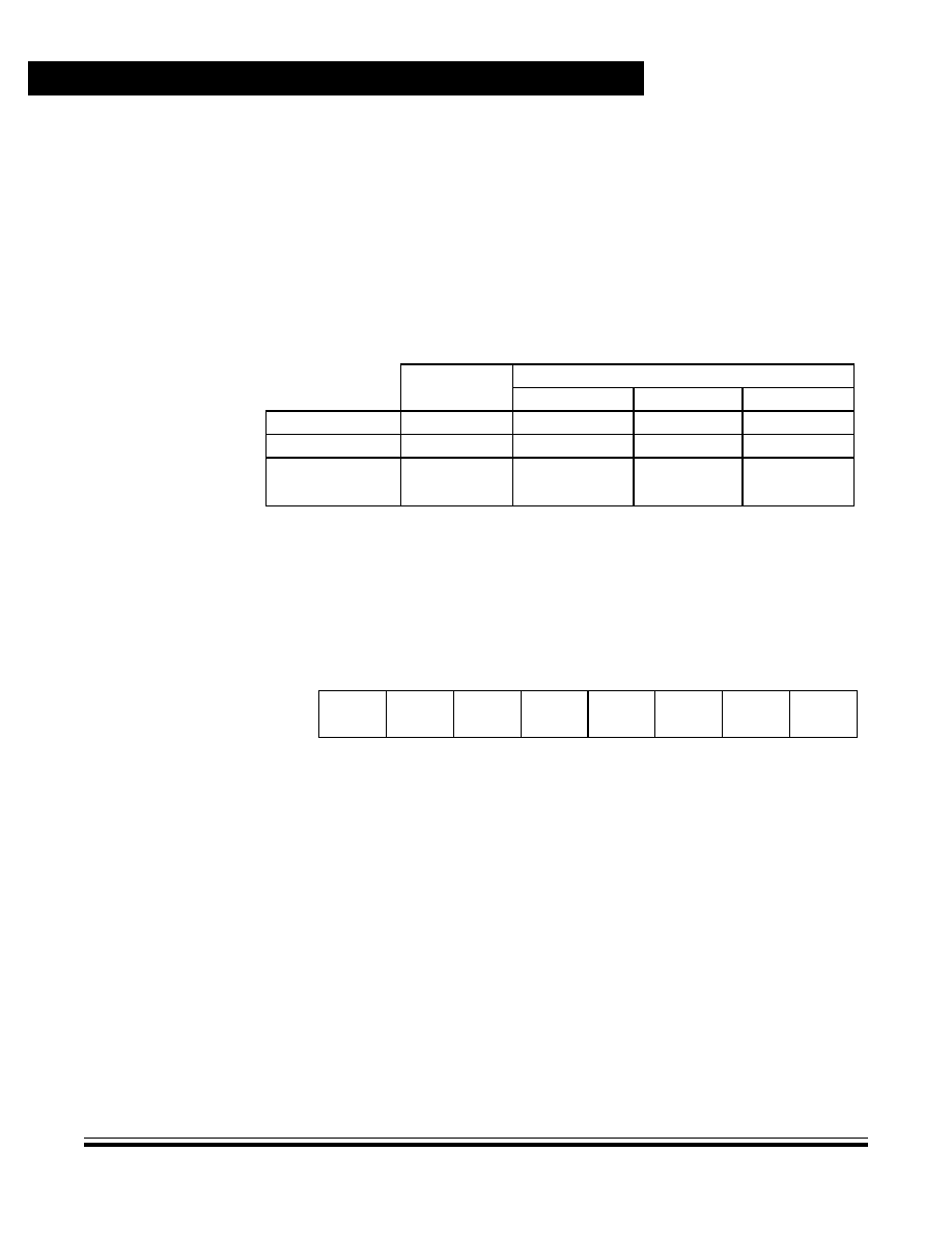
Table 8-7. Pulse Accumulator Timing in Gated Mode
Selected
Crystal
Common XTAL Frequencies
4.0 MHz
8.0 MHz
12.0 MHz
CPU Clock
(E)
1.0 MHz
2.0 MHz
3.0 MHz
Cycle Time
(1/E)
1000 ns
500 ns
333 ns
(E/26)
(E/214)
1 count -
overflow -
64.0 s
16.384 ms
32.0 s
8.192 ms
21.33 s
5.461 ms
Address:
$0026
Bit 7
654321
Bit 0
Read:
DDRA7
PAEN
PAMOD
PEDGE
DDRA3
I4/O5
RTR1
RTR0
Write:
Reset:
00000000
Figure 8-20. Pulse Accumulator Control Register (PACTL)
相關(guān)PDF資料 |
PDF描述 |
|---|---|
| MC68HC711D3MP2 | 8-BIT, OTPROM, 2 MHz, MICROCONTROLLER, PDIP40 |
| MC68HC711D3S | 8-BIT, UVPROM, 2.1 MHz, MICROCONTROLLER, CDIP40 |
| MC68HC711D3FN | 8-BIT, OTPROM, 2.1 MHz, MICROCONTROLLER, PQCC44 |
| MC68HC711G5CFN | 8-BIT, OTPROM, 2.1 MHz, MICROCONTROLLER, PQCC84 |
| MC68HC11G7CFN | 8-BIT, MROM, 2.1 MHz, MICROCONTROLLER, PQCC84 |
相關(guān)代理商/技術(shù)參數(shù) |
參數(shù)描述 |
|---|---|
| MCC68HRC705JP7 | 制造商:Motorola Inc 功能描述: |
| MCC6M10 | 制造商:Thomas & Betts 功能描述:METRIC CU CONNECTOR 6SQMM M10 STUD |
| MCC6M3 | 制造商:Thomas & Betts 功能描述:METRIC CU CONNECTOR 6SQMM M3 STUD |
| MCC6M3.5 | 制造商:Thomas & Betts 功能描述:METRIC CU CONNECTOR 6SQMM 3.5 STUD |
| MCC6M4 | 制造商:Thomas & Betts 功能描述:METRIC CONNECTOR 6SQMM M4 STUD |
發(fā)布緊急采購(gòu),3分鐘左右您將得到回復(fù)。