- 您現(xiàn)在的位置:買賣IC網(wǎng) > PDF目錄298813 > AD9874ABSTZ (ANALOG DEVICES INC) SPECIALTY TELECOM CIRCUIT, PQFP48 PDF資料下載
參數(shù)資料
| 型號: | AD9874ABSTZ |
| 廠商: | ANALOG DEVICES INC |
| 元件分類: | 通信及網(wǎng)絡 |
| 英文描述: | SPECIALTY TELECOM CIRCUIT, PQFP48 |
| 封裝: | PLASTIC, MS-026BBC, LQFP-48 |
| 文件頁數(shù): | 5/40頁 |
| 文件大?。?/td> | 1682K |
| 代理商: | AD9874ABSTZ |
第1頁第2頁第3頁第4頁當前第5頁第6頁第7頁第8頁第9頁第10頁第11頁第12頁第13頁第14頁第15頁第16頁第17頁第18頁第19頁第20頁第21頁第22頁第23頁第24頁第25頁第26頁第27頁第28頁第29頁第30頁第31頁第32頁第33頁第34頁第35頁第36頁第37頁第38頁第39頁第40頁
REV. A
AD9874
–13–
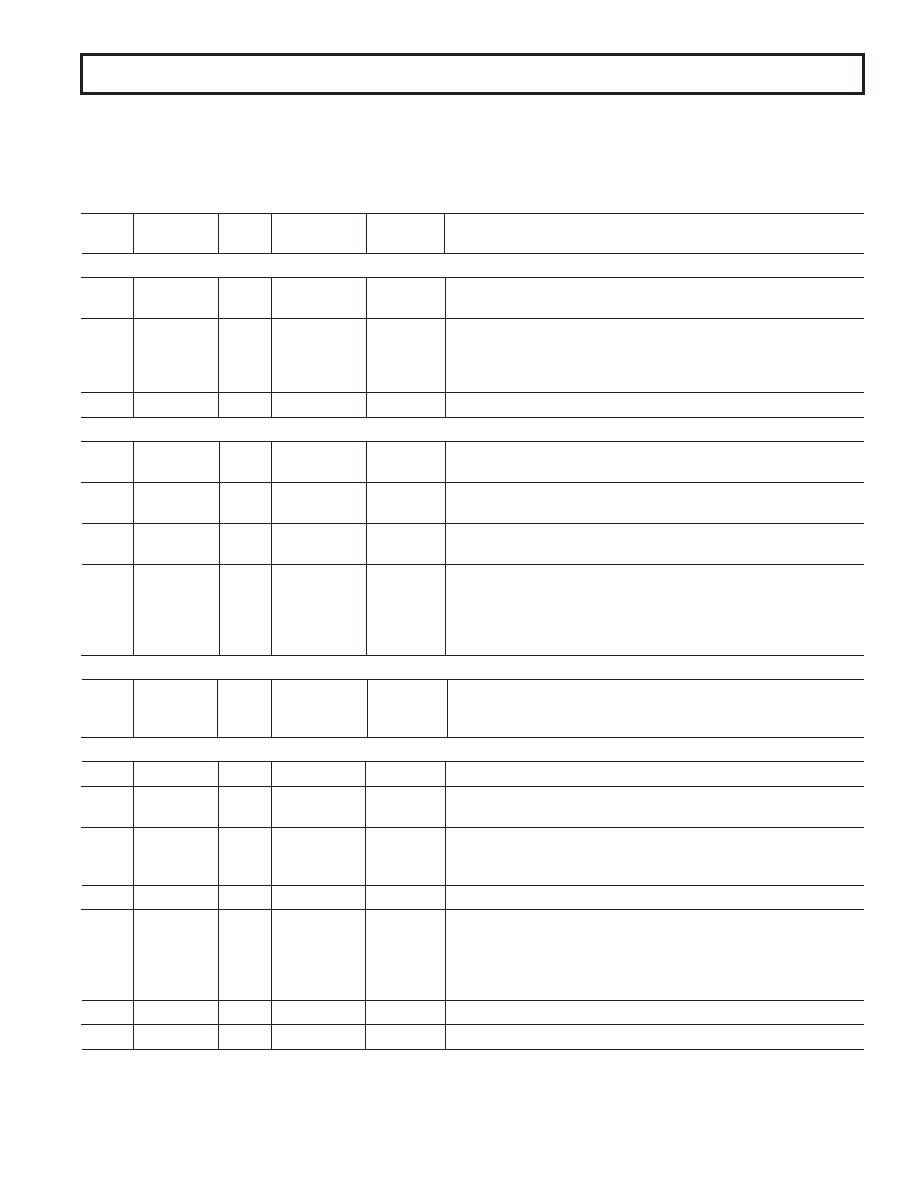
SERIAL PERIPHERAL INTERFACE (SPI)
The serial peripheral interface (SPI) is a bidirectional serial port. It is used to load configuration information into the registers listed
below as well as to read back their contents. Table I provides a list of the registers that may be programmed through the SPI port.
Addresses and default values are given in hexadecimal form.
Table I. SPI Address Map
Address
Bit
(Hex)
Breakdown Width
Default Value Name
Description
POWER CONTROL REGISTERS
0x00
(7:0)
8
0xFF
STBY
Standby Control Bits (REF, LO, CKO, CK, GC, LNAMX, Unused,
and ADC).
0x01
(7:6)
2
0
LNAB
LNA Bias Current (0 = 0.5 mA, 1 = 1 mA, 2 = 2 mA, 3 = 3 mA).
(5:4)
2
0
MIXB
Mixer Bias Current (0 = 0.5 mA, 1 = 1.5 mA, 2 = 2.7 mA, 3 = 4 mA).
(3:2)
2
0
CKOB
CK Oscillator Bias (0 = 0.25 mA, 1 = 0.35 mA, 2 = 0.40 mA, 3 = 0.65 mA).
(1:0)
2
0
ADCB
Do not use.
0x02
(7:0)
8
0x00
TEST
Factory Test Mode. Do not use.
AGC
0x03
(7)
1
0
ATTEN
Apply 16 dB attenuation in the front end.
(6:0)
7
0x00
AGCG(14:8)
AGC Attenuation Setting (7 MSB of a 15-Bit Unsigned Word).
0x04
(7:0)
8
0x00
AGCG(7:0)
AGC Attenuation Setting (8 LSB of a 15-Bit Unsigned Word).
Default corresponds to maximum gain.
0x05
(7:4)
4
0
AGCA
AGC Attack Bandwidth Setting. Default yields 50 Hz raw loop bandwidth.
(3:0)
4
0
AGCD
AGC Decay Time Setting. Default is decay time = attack time.
0x06
(7)
1
0
AGCV
Enable digital VGA to increase AGC range by 12 dB.
(6:4)
3
0
AGCO
AGC Overload Update Setting. Default is slowest update.
(3)
1
0
AGCF
Fast AGC (Minimizes resistance seen between GCP and GCN).
(2:0)
3
0
AGCR
AGC Enable/Reference Level (Disabled, 3 dB, 6 dB, 9 dB, 12 dB, 15 dB
below Clip).
DECIMATION FACTOR
0x07
(7:5)
3
Unused
(4)
1
0
K
Decimation Factor = 60
(M + 1), if K = 0; 48
(M + 1), if K = 1.
(3:0)
4
M
Default is Decimate-by-300.
LO SYNTHESIZER
0x08
(5:0)
6
0x00
LOR(13:8)
Reference Frequency Divisor (6 MSB of a 14-Bit Word).
0x09
(7:0)
8
0x38
LOR(7:0)
Reference Frequency Divisor (8 LSB of a 14-Bit Word).
Default (56) yields 300 kHz from fREF = 16.8 MHz.
0x0A
(7:5)
3
0x5
LOA
“A” Counter (Prescaler Control Counter).
(4:0)
5
0x00
LOB(12:8)
“B” Counter MSB (5 MSB of a 13-Bit Word).
Default LOA and LOB values yield 300 kHz from 73.35 MHz to 2.25 MHz.
0x0B
(7:0)
8
0x1D
LOB(7:0)
“B” Counter LSB (8 LSB of a 13-Bit Word).
0x0C
(6)
1
0
LOF
Enable fast acquire.
(5)
1
0
LOINV
Invert charge pump (0 = source current to increase VCO frequency).
(4:2)
3
0
LOI
Charge Pump Current in Normal Operation. IPUMP = (LOI + 1)
0.625 mA.
(1:0)
2
3
LOTM
Manual Control of LO Charge Pump (0 = Off, 1 = Up, 2 = Down,
3 = Normal).
0x0D
(5:0)
4
0x0
LOFA(13:8) LO Fast Acquire Time Unit (6 MSB of a 14-Bit Word).
0x0E
(7:0)
8
0x04
LOFA(7:0)
LO Fast Acquire Time Unit (8 LSB of a 14-Bit Word).
相關PDF資料 |
PDF描述 |
|---|---|
| AD9874ABSTZRL | SPECIALTY TELECOM CIRCUIT, PQFP48 |
| ADC0831CIWM | 1-CH 8-BIT SUCCESSIVE APPROXIMATION ADC, SERIAL ACCESS, PDSO14 |
| ADE7116ASTZF8-RL | SPECIALTY ANALOG CIRCUIT, PQFP64 |
| ADE7753ARSZRL | SPECIALTY ANALOG CIRCUIT, PDSO20 |
| ADEX-R10+ | 10 MHz - 1000 MHz RF/MICROWAVE DOUBLE BALANCED MIXER, 8.3 dB CONVERSION LOSS-MAX |
相關代理商/技術參數(shù) |
參數(shù)描述 |
|---|---|
| AD9874BST | 制造商:Rochester Electronics LLC 功能描述:- Tape and Reel |
| AD9874EB | 制造商:AD 制造商全稱:Analog Devices 功能描述:IF Digitizing Subsystem |
| AD9874-EB | 制造商:Analog Devices 功能描述: |
| AD9874-EBZ | 功能描述:BOARD EVAL FOR AD9874 制造商:analog devices inc. 系列:- 零件狀態(tài):有效 類型:數(shù)字轉換器 頻率:10MHz ~ 300MHz 配套使用產(chǎn)品/相關產(chǎn)品:AD9874 所含物品:板 標準包裝:1 |
| AD9875 | 制造商:AD 制造商全稱:Analog Devices 功能描述:Broadband Modem Mixed-Signal Front End |
發(fā)布緊急采購,3分鐘左右您將得到回復。