- 您現(xiàn)在的位置:買賣IC網(wǎng) > PDF目錄370034 > 28222-13 (Conexant Systems, Inc.) ATM Transmitter/Receiver with UTOPIA Interface PDF資料下載
參數(shù)資料
| 型號(hào): | 28222-13 |
| 廠商: | Conexant Systems, Inc. |
| 英文描述: | ATM Transmitter/Receiver with UTOPIA Interface |
| 中文描述: | 自動(dòng)柜員機(jī)發(fā)射機(jī)/接收機(jī)的UTOPIA接口 |
| 文件頁(yè)數(shù): | 41/161頁(yè) |
| 文件大?。?/td> | 1832K |
| 代理商: | 28222-13 |
第1頁(yè)第2頁(yè)第3頁(yè)第4頁(yè)第5頁(yè)第6頁(yè)第7頁(yè)第8頁(yè)第9頁(yè)第10頁(yè)第11頁(yè)第12頁(yè)第13頁(yè)第14頁(yè)第15頁(yè)第16頁(yè)第17頁(yè)第18頁(yè)第19頁(yè)第20頁(yè)第21頁(yè)第22頁(yè)第23頁(yè)第24頁(yè)第25頁(yè)第26頁(yè)第27頁(yè)第28頁(yè)第29頁(yè)第30頁(yè)第31頁(yè)第32頁(yè)第33頁(yè)第34頁(yè)第35頁(yè)第36頁(yè)第37頁(yè)第38頁(yè)第39頁(yè)第40頁(yè)當(dāng)前第41頁(yè)第42頁(yè)第43頁(yè)第44頁(yè)第45頁(yè)第46頁(yè)第47頁(yè)第48頁(yè)第49頁(yè)第50頁(yè)第51頁(yè)第52頁(yè)第53頁(yè)第54頁(yè)第55頁(yè)第56頁(yè)第57頁(yè)第58頁(yè)第59頁(yè)第60頁(yè)第61頁(yè)第62頁(yè)第63頁(yè)第64頁(yè)第65頁(yè)第66頁(yè)第67頁(yè)第68頁(yè)第69頁(yè)第70頁(yè)第71頁(yè)第72頁(yè)第73頁(yè)第74頁(yè)第75頁(yè)第76頁(yè)第77頁(yè)第78頁(yè)第79頁(yè)第80頁(yè)第81頁(yè)第82頁(yè)第83頁(yè)第84頁(yè)第85頁(yè)第86頁(yè)第87頁(yè)第88頁(yè)第89頁(yè)第90頁(yè)第91頁(yè)第92頁(yè)第93頁(yè)第94頁(yè)第95頁(yè)第96頁(yè)第97頁(yè)第98頁(yè)第99頁(yè)第100頁(yè)第101頁(yè)第102頁(yè)第103頁(yè)第104頁(yè)第105頁(yè)第106頁(yè)第107頁(yè)第108頁(yè)第109頁(yè)第110頁(yè)第111頁(yè)第112頁(yè)第113頁(yè)第114頁(yè)第115頁(yè)第116頁(yè)第117頁(yè)第118頁(yè)第119頁(yè)第120頁(yè)第121頁(yè)第122頁(yè)第123頁(yè)第124頁(yè)第125頁(yè)第126頁(yè)第127頁(yè)第128頁(yè)第129頁(yè)第130頁(yè)第131頁(yè)第132頁(yè)第133頁(yè)第134頁(yè)第135頁(yè)第136頁(yè)第137頁(yè)第138頁(yè)第139頁(yè)第140頁(yè)第141頁(yè)第142頁(yè)第143頁(yè)第144頁(yè)第145頁(yè)第146頁(yè)第147頁(yè)第148頁(yè)第149頁(yè)第150頁(yè)第151頁(yè)第152頁(yè)第153頁(yè)第154頁(yè)第155頁(yè)第156頁(yè)第157頁(yè)第158頁(yè)第159頁(yè)第160頁(yè)第161頁(yè)

Five modes are provided for receiver framing operation: DS3, G.751 E3, G.832
E3/E4, STS-1, and STS-3c/STM-1.
In DS3 mode, a
parallel-search framing circuit recovers the subframe and
M-frame alignments in the DS3 signal. Framing is initiated by an out-of-frame
condition as determined by the receiver frame bit-check circuitry. When 3 out of
16 consecutive subframing (F) bits are in error or when 2 out of 3 consecutive
M-frames have M bit errors, an out-of-frame condition is declared.
In G.751 E3 mode, a
serial search for the 10-bit FAS pattern (1111 0100 00) is
conducted. When three consecutive correct patterns are found, the receiver is
declared to be in frame. An out-of-frame condition is declared when four
consecutive incorrect FAS patterns are detected.
In G.804 E3/E4 and STS-1/STS-3c/STM-1 modes, an octet alignment by the
serial-to-parallel conversion circuit is found in conjunction with an octet search
for the SONET A1/A2 framing pattern (which is the same pattern as, but not
related to, the PLCP A1/A2 bytes). When two consecutive good patterns are
found, the receiver is declared to be in frame. An out-of-frame (OOF) condition is
declared when four consecutive incorrect A1/A2 patterns are detected.
In STS-3c/STM-1 mode, an octet alignment by the serial-to-parallel
conversion circuit is found in conjunction with an octet search for the third A1
and the first A2 octets.
In STS-1 Mode, if STS-1 Stuffing Option [bit 15] in CONFIG_1 [0x00] is set,
then columns 30 and 59 in the payload envelope are stuff columns, and these
octets will not be interpreted as ATM cell octets. If this bit is not set, then all 86
columns of the SPE will be interpreted as ATM cell octets.
CN8223
2.0 Functional Description
ATM Transmitter/Receiver with UTOPIA Interface
2.2 Line Framers
100046C
Conexant
2-7
2.2.2.1 High-Speed
PECL Receive Interface
STS-3c, STM-1 and E4 use the high-speed PECL interface. This mode is used in
any case where an external LIU/decoder is used (such as E4 and STS-3c/STM-1
CMI decoding). If the mode is set to E4 or STS-3c/STM-1 in CONFIG_1, then
the inputs are taken from the
“
HS
±
”
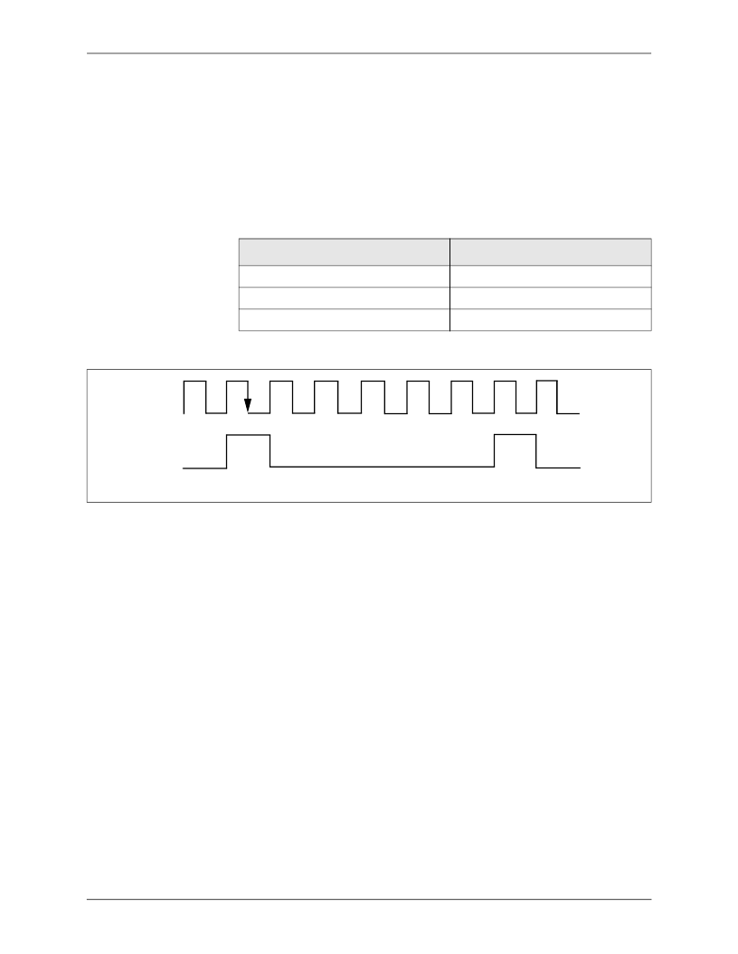
versions of the input pins. RXDATI input is
sampled on the falling edge of RXCKI. RXDATI can be sampled on the rising
edge of the input clock by setting the Invert RX Clock Sampling bit.
Table 2-5
lists the connections for internal framer Rx with the encoder disabled;
Figure 2-6
illustrates the timing with the coder disabled.
2.2.2.2 Receiver
Framing Operation
Table 2-5. Connections for Internal Framer Rx, Encoder Disabled (STS-3c, STM-1, E4)
Signal Name
Connect to CN8223 Pin
Receive Clock Input (RXCKI)
RXCKI or RXCKI_HS±
Receive Data (RXDATI)
RXIN[0] or RXIN_HS±
Receive Loss of Signal (RXLOS~)
RXIN[4]
Figure 2-6. Timing for Internal Framer Receiver, Encoder Disabled
RXCKI
RXDATI
8
相關(guān)PDF資料 |
PDF描述 |
|---|---|
| 28222-14 | ATM Transmitter/Receiver with UTOPIA Interface |
| 28233-11 | ATM Transmitter/Receiver with UTOPIA Interface |
| 28C010TRPDB-12 | 150 x 32 pixel format, LED Backlight available |
| 28C010TRT1DE-15 | 1 Megabit (128K x 8-Bit) EEPROM |
| 28C010TRT1DE-20 | 1 Megabit (128K x 8-Bit) EEPROM |
相關(guān)代理商/技術(shù)參數(shù) |
參數(shù)描述 |
|---|---|
| 28222-14 | 制造商:CONEXANT 制造商全稱:CONEXANT 功能描述:ATM Transmitter/Receiver with UTOPIA Interface |
| 282222-003 | 制造商:TE Connectivity 功能描述:81044/12-16-2 - Cable Rools/Shrink Tubing |
| 282223-003 | 制造商:TE Connectivity 功能描述:81044/12-16-3 - Cable Rools/Shrink Tubing |
| 282224-003 | 制造商:TE Connectivity 功能描述:81044/12-16-4 - Cable Rools/Shrink Tubing |
| 282224-1 | 功能描述:汽車連接器 ECONOSEAL RCPT CONT .5MM RoHS:否 制造商:Amphenol SINE Systems 產(chǎn)品:Contacts 系列:ATP 位置數(shù)量: 型式:Female 安裝風(fēng)格: 端接類型: 觸點(diǎn)電鍍:Nickel |
發(fā)布緊急采購(gòu),3分鐘左右您將得到回復(fù)。