- 您現(xiàn)在的位置:買賣IC網(wǎng) > PDF目錄360516 > 7544 3.3V LDO POSITVE VOLTAGE REGULATOR 2% TOL. PDF資料下載
參數(shù)資料
| 型號(hào): | 7544 |
| 英文描述: | 3.3V LDO POSITVE VOLTAGE REGULATOR 2% TOL. |
| 中文描述: | 7544Group數(shù)據(jù)表數(shù)據(jù)表503K/JUN.25.03 |
| 文件頁(yè)數(shù): | 19/54頁(yè) |
| 文件大小: | 503K |
| 代理商: | 7544 |
第1頁(yè)第2頁(yè)第3頁(yè)第4頁(yè)第5頁(yè)第6頁(yè)第7頁(yè)第8頁(yè)第9頁(yè)第10頁(yè)第11頁(yè)第12頁(yè)第13頁(yè)第14頁(yè)第15頁(yè)第16頁(yè)第17頁(yè)第18頁(yè)當(dāng)前第19頁(yè)第20頁(yè)第21頁(yè)第22頁(yè)第23頁(yè)第24頁(yè)第25頁(yè)第26頁(yè)第27頁(yè)第28頁(yè)第29頁(yè)第30頁(yè)第31頁(yè)第32頁(yè)第33頁(yè)第34頁(yè)第35頁(yè)第36頁(yè)第37頁(yè)第38頁(yè)第39頁(yè)第40頁(yè)第41頁(yè)第42頁(yè)第43頁(yè)第44頁(yè)第45頁(yè)第46頁(yè)第47頁(yè)第48頁(yè)第49頁(yè)第50頁(yè)第51頁(yè)第52頁(yè)第53頁(yè)第54頁(yè)
Rev.1.02 2003.06.25 page 19 of 53
7544 Group
PRELIMINARY
Notice: This is not a final specification.
Some parametric limits are subject to change.
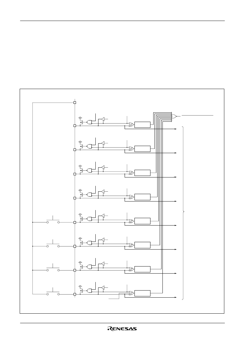
Key Input Interrupt (Key-On Wake-Up)
A key-on wake-up interrupt request is generated by applying
“
L
”
level to any pin of port P0 that has been set to input mode.
In other words, it is generated when the AND of input level goes
from
“
1
”
to
“
0
”
. An example of using a key input interrupt is shown
in Figure 19, where an interrupt request is generated by pressing
one of the keys provided as an active-low key matrix which uses
ports P0
0
to P0
3
as input ports.
Fig. 19 Connection example when using key input interrupt and port P0 block diagram
Port PXx
“
L
”
level output
PULL register
bit 3 =
“
0
”
Port P0
7
latch
Port P0
7
Direction register =
“
1
”
**
*
P0
7
output
Key input interrupt request
Port P0
Input read circuit
* P-channel transistor for pull-up
** CMOS output buffer
PULL register
bit 3 =
“
0
”
Port P0
6
latch
Port P0
6
Direction register =
“
1
”
**
*
P0
6
output
PULL register
bit 3 =
“
0
”
Port P0
5
latch
Port P0
5
Direction register =
“
1
”
**
*
P0
5
output
PULL register
bit 3 =
“
0
”
Port P0
4
latch
Port P0
4
Direction register =
“
1
”
**
*
P0
4
output
PULL register
bit 2 =
“
1
”
Port P0
3
latch
Port P0
3
Direction register =
“
0
”
**
*
P0
3
input
PULL register
bit 2 =
“
1
”
Port P0
2
latch
Port P0
2
Direction register =
“
0
”
**
*
P0
2
input
PULL register
bit 1 =
“
1
”
Port P0
1
latch
Port P0
1
Direction register =
“
0
”
**
*
P0
1
input
PULL register
bit 0 =
“
1
”
Port P0
0
latch
Port P0
0
Direction register =
“
0
”
**
*
P0
0
input
Falling edge
detection
Falling edge
detection
Falling edge
detection
Falling edge
detection
Falling edge
detection
Falling edge
detection
Falling edge
detection
Falling edge
detection
Port P0
0
key-on wakeup
selection bit
相關(guān)PDF資料 |
PDF描述 |
|---|---|
| 75450PC | Peripheral IC |
| D122D | Converter IC |
| D347D | Logic IC |
| D348D | Logic IC |
| 7545ARPDS-2 | HIGH VOLTAGE, LOW QUIESCENT CURRENT LDO, -40C to +125C, 3-SOT-89, T/R |
相關(guān)代理商/技術(shù)參數(shù) |
參數(shù)描述 |
|---|---|
| 754-4.47M | 制造商:OSCILENT 制造商全稱:Oscilent Corporation 功能描述:Ceramic Trap Double/Triple Peak |
| 754-4.6M | 制造商:OSCILENT 制造商全稱:Oscilent Corporation 功能描述:Ceramic Trap Double/Triple Peak |
| 754-4007-0 | 制造商:ROCK 功能描述: |
| 75-440-6 | 制造商:ATM 制造商全稱:ATM 功能描述:STANDARD GAIN HORN |
| 75-440-X | 制造商:ATM 制造商全稱:ATM 功能描述:HORN MOUNT APPLICATIONS |
發(fā)布緊急采購(gòu),3分鐘左右您將得到回復(fù)。