- 您現(xiàn)在的位置:買賣IC網(wǎng) > PDF目錄359352 > VCT3801A (MICRONAS SEMICONDUCTOR HOLDING AG) Video/Controller/Teletext IC Family PDF資料下載
參數(shù)資料
| 型號(hào): | VCT3801A |
| 廠商: | MICRONAS SEMICONDUCTOR HOLDING AG |
| 英文描述: | Video/Controller/Teletext IC Family |
| 中文描述: | 視頻/控制/圖文電視IC系列 |
| 文件頁(yè)數(shù): | 27/172頁(yè) |
| 文件大小: | 2243K |
| 代理商: | VCT3801A |
第1頁(yè)第2頁(yè)第3頁(yè)第4頁(yè)第5頁(yè)第6頁(yè)第7頁(yè)第8頁(yè)第9頁(yè)第10頁(yè)第11頁(yè)第12頁(yè)第13頁(yè)第14頁(yè)第15頁(yè)第16頁(yè)第17頁(yè)第18頁(yè)第19頁(yè)第20頁(yè)第21頁(yè)第22頁(yè)第23頁(yè)第24頁(yè)第25頁(yè)第26頁(yè)當(dāng)前第27頁(yè)第28頁(yè)第29頁(yè)第30頁(yè)第31頁(yè)第32頁(yè)第33頁(yè)第34頁(yè)第35頁(yè)第36頁(yè)第37頁(yè)第38頁(yè)第39頁(yè)第40頁(yè)第41頁(yè)第42頁(yè)第43頁(yè)第44頁(yè)第45頁(yè)第46頁(yè)第47頁(yè)第48頁(yè)第49頁(yè)第50頁(yè)第51頁(yè)第52頁(yè)第53頁(yè)第54頁(yè)第55頁(yè)第56頁(yè)第57頁(yè)第58頁(yè)第59頁(yè)第60頁(yè)第61頁(yè)第62頁(yè)第63頁(yè)第64頁(yè)第65頁(yè)第66頁(yè)第67頁(yè)第68頁(yè)第69頁(yè)第70頁(yè)第71頁(yè)第72頁(yè)第73頁(yè)第74頁(yè)第75頁(yè)第76頁(yè)第77頁(yè)第78頁(yè)第79頁(yè)第80頁(yè)第81頁(yè)第82頁(yè)第83頁(yè)第84頁(yè)第85頁(yè)第86頁(yè)第87頁(yè)第88頁(yè)第89頁(yè)第90頁(yè)第91頁(yè)第92頁(yè)第93頁(yè)第94頁(yè)第95頁(yè)第96頁(yè)第97頁(yè)第98頁(yè)第99頁(yè)第100頁(yè)第101頁(yè)第102頁(yè)第103頁(yè)第104頁(yè)第105頁(yè)第106頁(yè)第107頁(yè)第108頁(yè)第109頁(yè)第110頁(yè)第111頁(yè)第112頁(yè)第113頁(yè)第114頁(yè)第115頁(yè)第116頁(yè)第117頁(yè)第118頁(yè)第119頁(yè)第120頁(yè)第121頁(yè)第122頁(yè)第123頁(yè)第124頁(yè)第125頁(yè)第126頁(yè)第127頁(yè)第128頁(yè)第129頁(yè)第130頁(yè)第131頁(yè)第132頁(yè)第133頁(yè)第134頁(yè)第135頁(yè)第136頁(yè)第137頁(yè)第138頁(yè)第139頁(yè)第140頁(yè)第141頁(yè)第142頁(yè)第143頁(yè)第144頁(yè)第145頁(yè)第146頁(yè)第147頁(yè)第148頁(yè)第149頁(yè)第150頁(yè)第151頁(yè)第152頁(yè)第153頁(yè)第154頁(yè)第155頁(yè)第156頁(yè)第157頁(yè)第158頁(yè)第159頁(yè)第160頁(yè)第161頁(yè)第162頁(yè)第163頁(yè)第164頁(yè)第165頁(yè)第166頁(yè)第167頁(yè)第168頁(yè)第169頁(yè)第170頁(yè)第171頁(yè)第172頁(yè)
ADVANCE INFORMATION
VCT 38xxA
Micronas
27
2.11.3.Average Beam Current Limiter
The average beam current limiter (BCL) uses the
SENSE input for the beam current measurement. The
BCL uses a different filter to average the beam current
during the active picture. The filter bandwidth is
approx. 2 kHz. The beam current limiter has an auto-
matic offset adjustment that is active two lines before
the first cutoff measurement line.
The beam current limiter function is located in the
front-end. The data exchange between the front-end
and the back-end is done via a single-wire serial inter-
face.
The beam current limiter allows the setting of a thresh-
old current. If the beam current is above the threshold,
the excess current is low-pass filtered and used to
attenuate the RGB outputs by adjusting the white-drive
multipliers for the internal (digital) RGB signals, and
the analog contrast multipliers for the analog RGB
inputs, respectively. The lower limit of the attenuator is
programmable, thus a minimum contrast can always
be set. During the tube measurement, the ABL attenu-
ation is switched off. After the white-drive measure-
ment line it takes 3 lines to switch back to BCL limited
drives and brightness.
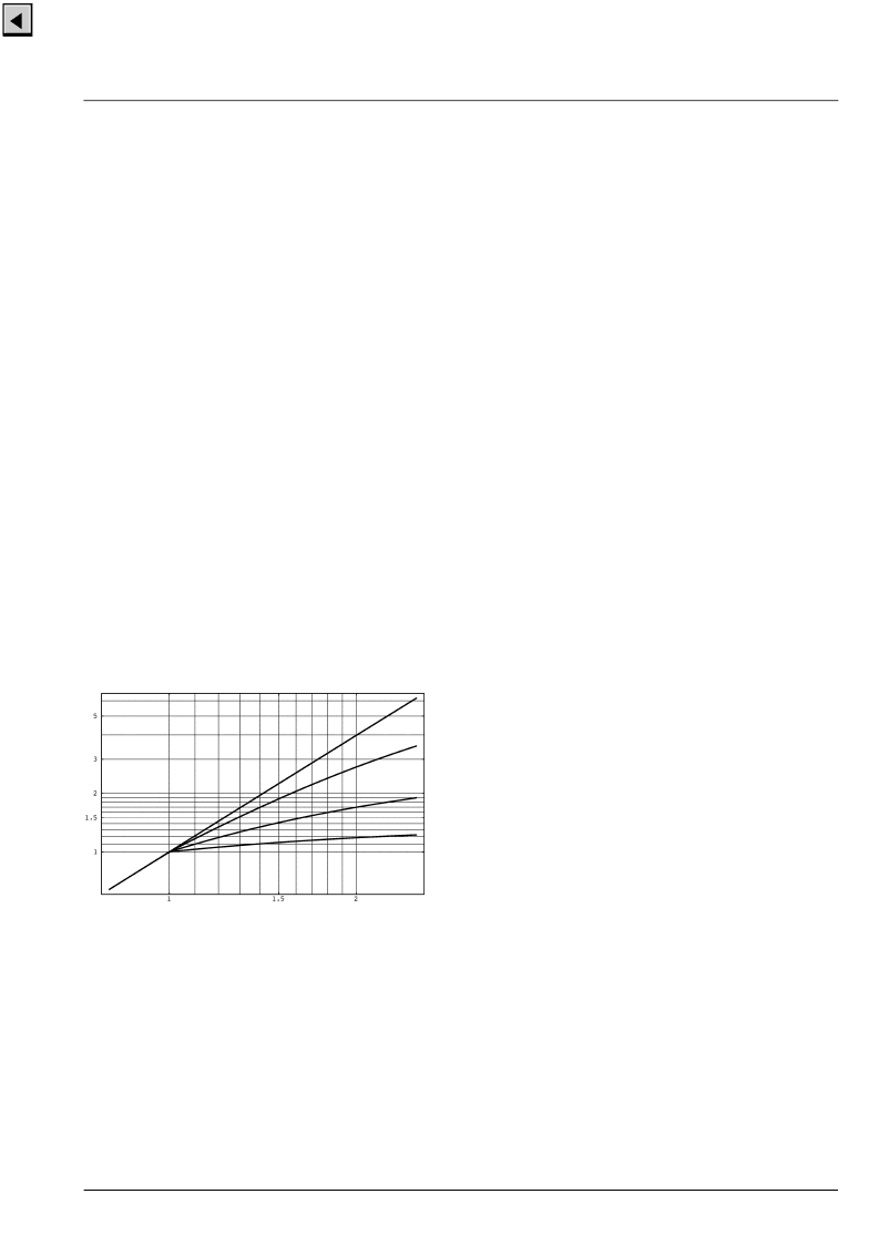
Typical characteristics of the ABL for different loop
gains are shown in Fig. 2–22; for this example the tube
has been assumed to have square law characteristics.
Fig. 2–22:
Beam current limiter characteristics:
beam current output vs. drive
BCL threshold: 1
2.11.4.Analog RGB Insertion
The VCT 38xxA allows insertion of external analog
RGB signals. The RGB signal is key-clamped and
inserted into the main RGB by the Fast-Blank switch.
The external RGB input can be overlaid or underlaid to
the digital picture. The external RGB signals can be
adjusted independently as regards DC level (bright-
ness) and magnitude (contrast).
All signals for analog RGB insertion (RIN, GIN, BIN,
FBLIN) must be synchronized to the horizontal flyback,
otherwise a horizontal jitter will be visible. The
VCT 38xxA has no means for timing correction of the
analog RGB input signals.
2.11.5.Fast-Blank Monitor
The presence of external analog RGB sources can be
detected by means of a Fast-Blank monitor. The status
of the Fast-Blank input can be monitored via an I
2
C
bus register. There is a 2 bit information, giving static
and dynamic indication of a Fast-Blank signal. The
static bit is directly reading the Fast-Blank input line,
whereas the dynamic bit is reading the status of a
flip-flop triggered by the negative edge of the Fast-
Blank signal.
With this monitor logic it is possible to detect if there is
an external RGB source active and if it is a full screen
insertion or only a box. The monitor logic is connected
directly to the FBLIN pin.
相關(guān)PDF資料 |
PDF描述 |
|---|---|
| VCU2133 | High-Speed coder/decoder IC |
| VCX2150A | Surface mount 15.88 mm SQ (.625 SQ) |
| VCX2154A | Surface mount 15.88 mm SQ (.625 SQ) |
| VCXO-105N | VCXO |
| VCXO-199 | VCXO |
相關(guān)代理商/技術(shù)參數(shù) |
參數(shù)描述 |
|---|---|
| VCT3802A | 制造商:MICRONAS 制造商全稱:MICRONAS 功能描述:Video/Controller/Teletext IC Family |
| VCT3803A | 制造商:MICRONAS 制造商全稱:MICRONAS 功能描述:Video/Controller/Teletext IC Family |
| VCT3804A | 制造商:MICRONAS 制造商全稱:MICRONAS 功能描述:Video/Controller/Teletext IC Family |
| VCT3811A | 制造商:MICRONAS 制造商全稱:MICRONAS 功能描述:Video/Controller/Teletext IC Family |
| VCT3831A | 制造商:MICRONAS 制造商全稱:MICRONAS 功能描述:Video/Controller/Teletext IC Family |
發(fā)布緊急采購(gòu),3分鐘左右您將得到回復(fù)。