- 您現(xiàn)在的位置:買賣IC網(wǎng) > PDF目錄98302 > TSC2117IRGZT (TEXAS INSTRUMENTS INC) SPECIALTY CONSUMER CIRCUIT, QCC48 PDF資料下載
參數(shù)資料
| 型號: | TSC2117IRGZT |
| 廠商: | TEXAS INSTRUMENTS INC |
| 元件分類: | 消費家電 |
| 英文描述: | SPECIALTY CONSUMER CIRCUIT, QCC48 |
| 封裝: | 7 X 7 MM, GREEN, PLASTIC, VQFN-48 |
| 文件頁數(shù): | 27/192頁 |
| 文件大小: | 2728K |
| 代理商: | TSC2117IRGZT |
第1頁第2頁第3頁第4頁第5頁第6頁第7頁第8頁第9頁第10頁第11頁第12頁第13頁第14頁第15頁第16頁第17頁第18頁第19頁第20頁第21頁第22頁第23頁第24頁第25頁第26頁當(dāng)前第27頁第28頁第29頁第30頁第31頁第32頁第33頁第34頁第35頁第36頁第37頁第38頁第39頁第40頁第41頁第42頁第43頁第44頁第45頁第46頁第47頁第48頁第49頁第50頁第51頁第52頁第53頁第54頁第55頁第56頁第57頁第58頁第59頁第60頁第61頁第62頁第63頁第64頁第65頁第66頁第67頁第68頁第69頁第70頁第71頁第72頁第73頁第74頁第75頁第76頁第77頁第78頁第79頁第80頁第81頁第82頁第83頁第84頁第85頁第86頁第87頁第88頁第89頁第90頁第91頁第92頁第93頁第94頁第95頁第96頁第97頁第98頁第99頁第100頁第101頁第102頁第103頁第104頁第105頁第106頁第107頁第108頁第109頁第110頁第111頁第112頁第113頁第114頁第115頁第116頁第117頁第118頁第119頁第120頁第121頁第122頁第123頁第124頁第125頁第126頁第127頁第128頁第129頁第130頁第131頁第132頁第133頁第134頁第135頁第136頁第137頁第138頁第139頁第140頁第141頁第142頁第143頁第144頁第145頁第146頁第147頁第148頁第149頁第150頁第151頁第152頁第153頁第154頁第155頁第156頁第157頁第158頁第159頁第160頁第161頁第162頁第163頁第164頁第165頁第166頁第167頁第168頁第169頁第170頁第171頁第172頁第173頁第174頁第175頁第176頁第177頁第178頁第179頁第180頁第181頁第182頁第183頁第184頁第185頁第186頁第187頁第188頁第189頁第190頁第191頁第192頁
TSC2117
Low-Power Audio Codec With Embedded miniDSP, Stereo Class-D
Speaker Amplifier, and Smart Four-Wire Touch-Screen Controller
SLAS550A – APRIL 2009 – REVISED JUNE 2009
www.ti.com
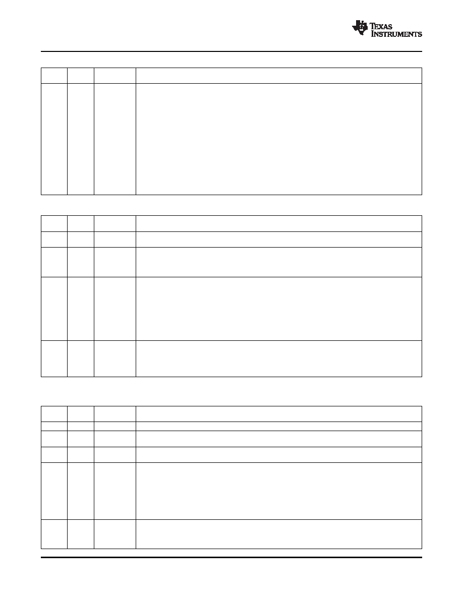
Page 0/Register 66: DAC Right Volume Control
READ/
RESET
BIT
DESCRIPTION
WRITE
VALUE
D7–D0
R/W
0000 0000
127 to 49: Reserved. Do not write these sequences to these bits.
48: Right-channel DAC digital gain = 24 dB
47: Right-channel DAC digital gain = 23.5 dB
46: Right-channel DAC digital gain = 23 dB
...
36: Right-channel DAC digital gain = 18 dB
35: Right-channel DAC digital gain = 17.5 dB
34: Right-channel DAC digital gain = 17 dB
...
1: Right-channel DAC digital gain = 0.5 dB
0: Right-channel DAC digital gain = 0 dB
–1: Right-channel DAC digital gain = –0.5 dB
...
–126: Right-channel DAC digital gain = –63 dB
–127: Right-channel DAC digital gain = –63.5 dB
–128: Reserved
Page 0/Register 67: Headset Detection
READ/
RESET
BIT
DESCRIPTION
WRITE
VALUE
D7
R/W
0
0: Headset detection disabled
1: Headset detection enabled
D6–D5
R
XX
00: No headset detected
01: Headset without microphone is detected
10: Reserved
11: Headset with microphone is detected
D4–D2
R/W
000
Debounce Programming for Glitch Rejection During Headset Detection(1)
000: 16 ms (sampled with 2-ms clock)
001: 32 ms (sampled with 4-ms clock)
010: 64 ms (sampled with 8-ms clock)
011: 128 ms (sampled with 16-ms clock)
100: 256 ms (sampled with 32-ms clock)
101: 512 ms (sampled with 64-ms clock)
110: Reserved
111: Reserved
D1–D0
R/W
00
Debounce Programming for Glitch Rejection During Headset Button-Press Detection
00: 0 ms
01: 8 ms (sampled with 1-ms clock)
10: 16 ms (sampled with 2-ms clock)
11: 32 ms (sampled with 4-ms clock)
(1)
Note that these times are generated using the 1 MHz reference clock which is defined in page 3/register 16.
Page 0/Register 68: DRC Control 1
READ/
RESET
BIT
DESCRIPTION
WRITE
VALUE
D7
R/W
0
Reserved. Write only the reset value to these bits.
D6
R/W
0
0: DRC disabled for left channel
1: DRC enabled for left channel
D5
R/W
0
0: DRC disabled for right channel
1: DRC enabled for right channel
D4–D2
R/W
011
000: DRC threshold = –3 dB
001: DRC threshold = –6 dB
010: DRC threshold = –9 dB
011: DRC threshold = –12 dB
100: DRC threshold = –15 dB
101: DRC threshold = –18 dB
110: DRC threshold = –21 dB
111: DRC threshold = –24 dB
D1–D0
R/W
11
00: DRC hysteresis = 0 dB
01: DRC hysteresis = 1 dB
10: DRC hysteresis = 2 dB
11: DRC hysteresis = 3 dB
122
REGISTER MAP
相關(guān)PDF資料 |
PDF描述 |
|---|---|
| TSC2300IPAGG4 | SPECIALTY CONSUMER CIRCUIT, PQFP64 |
| TSC2300IPAGR | SPECIALTY CONSUMER CIRCUIT, PQFP64 |
| TSC2300IPAG | SPECIALTY CONSUMER CIRCUIT, PQFP64 |
| TSC2300IPAGRG4 | SPECIALTY CONSUMER CIRCUIT, PQFP64 |
| TSC2301IPAGR | SPECIALTY CONSUMER CIRCUIT, PQFP64 |
相關(guān)代理商/技術(shù)參數(shù) |
參數(shù)描述 |
|---|---|
| TSC2117IRGZT | 制造商:Texas Instruments 功能描述:Touch Screen Controller IC |
| TSC22 | 制造商:未知廠家 制造商全稱:未知廠家 功能描述:EURO TERMINAL BLOCKS |
| TSC2200 | 制造商:BB 制造商全稱:BB 功能描述:PDA ANALOG INTERFACE CIRCUIT |
| TSC2200EVM | 功能描述:觸摸傳感器開發(fā)工具 Touch Screen Contr Eval Mod RoHS:否 制造商:Cypress Semiconductor 工具用于評估: 接口類型: 工作電壓: 最大工作溫度: |
| TSC2200IPW | 功能描述:觸摸屏轉(zhuǎn)換器和控制器 Prog 4-Wire w/12-Bit 125KHz ADC & Key Ifc RoHS:否 制造商:Microchip Technology 類型:Resistive Touch Controllers 輸入類型:3 Key 數(shù)據(jù)速率:140 SPS 分辨率:10 bit 接口類型:4-Wire, 5-Wire, 8-Wire, I2C, SPI 電源電壓:2.5 V to 5.25 V 電源電流:17 mA 工作溫度:- 40 C to + 85 C 封裝 / 箱體:SSOP-20 |
發(fā)布緊急采購,3分鐘左右您將得到回復(fù)。