- 您現(xiàn)在的位置:買賣IC網(wǎng) > PDF目錄98302 > TSC2117IRGZT (TEXAS INSTRUMENTS INC) SPECIALTY CONSUMER CIRCUIT, QCC48 PDF資料下載
第1頁(yè)第2頁(yè)第3頁(yè)第4頁(yè)第5頁(yè)第6頁(yè)第7頁(yè)第8頁(yè)第9頁(yè)第10頁(yè)第11頁(yè)第12頁(yè)第13頁(yè)第14頁(yè)第15頁(yè)第16頁(yè)第17頁(yè)第18頁(yè)第19頁(yè)第20頁(yè)第21頁(yè)第22頁(yè)第23頁(yè)第24頁(yè)第25頁(yè)第26頁(yè)第27頁(yè)第28頁(yè)第29頁(yè)第30頁(yè)第31頁(yè)第32頁(yè)第33頁(yè)第34頁(yè)第35頁(yè)第36頁(yè)第37頁(yè)第38頁(yè)第39頁(yè)第40頁(yè)第41頁(yè)第42頁(yè)第43頁(yè)第44頁(yè)第45頁(yè)第46頁(yè)第47頁(yè)第48頁(yè)第49頁(yè)第50頁(yè)第51頁(yè)第52頁(yè)第53頁(yè)第54頁(yè)第55頁(yè)第56頁(yè)第57頁(yè)第58頁(yè)第59頁(yè)第60頁(yè)第61頁(yè)第62頁(yè)第63頁(yè)第64頁(yè)第65頁(yè)第66頁(yè)第67頁(yè)第68頁(yè)第69頁(yè)第70頁(yè)第71頁(yè)第72頁(yè)第73頁(yè)第74頁(yè)第75頁(yè)第76頁(yè)第77頁(yè)第78頁(yè)第79頁(yè)第80頁(yè)第81頁(yè)第82頁(yè)第83頁(yè)第84頁(yè)第85頁(yè)第86頁(yè)第87頁(yè)第88頁(yè)第89頁(yè)第90頁(yè)第91頁(yè)第92頁(yè)第93頁(yè)第94頁(yè)第95頁(yè)第96頁(yè)第97頁(yè)第98頁(yè)第99頁(yè)第100頁(yè)第101頁(yè)第102頁(yè)第103頁(yè)第104頁(yè)第105頁(yè)第106頁(yè)第107頁(yè)第108頁(yè)第109頁(yè)第110頁(yè)第111頁(yè)第112頁(yè)第113頁(yè)第114頁(yè)第115頁(yè)第116頁(yè)第117頁(yè)第118頁(yè)第119頁(yè)第120頁(yè)第121頁(yè)第122頁(yè)第123頁(yè)第124頁(yè)第125頁(yè)第126頁(yè)第127頁(yè)第128頁(yè)第129頁(yè)第130頁(yè)第131頁(yè)第132頁(yè)第133頁(yè)第134頁(yè)第135頁(yè)第136頁(yè)第137頁(yè)第138頁(yè)第139頁(yè)第140頁(yè)第141頁(yè)第142頁(yè)第143頁(yè)第144頁(yè)第145頁(yè)第146頁(yè)第147頁(yè)第148頁(yè)第149頁(yè)第150頁(yè)第151頁(yè)第152頁(yè)第153頁(yè)第154頁(yè)第155頁(yè)第156頁(yè)第157頁(yè)第158頁(yè)第159頁(yè)第160頁(yè)第161頁(yè)第162頁(yè)第163頁(yè)第164頁(yè)第165頁(yè)第166頁(yè)第167頁(yè)第168頁(yè)第169頁(yè)第170頁(yè)第171頁(yè)第172頁(yè)第173頁(yè)第174頁(yè)第175頁(yè)第176頁(yè)第177頁(yè)第178頁(yè)第179頁(yè)第180頁(yè)第181頁(yè)當(dāng)前第182頁(yè)第183頁(yè)第184頁(yè)第185頁(yè)第186頁(yè)第187頁(yè)第188頁(yè)第189頁(yè)第190頁(yè)第191頁(yè)第192頁(yè)
(3)
DAC to headphone-out PSRR measurement is calculated as
Supp
10
DACOUT
VSIG
PSRR
20 log
V
é
ù
=
ê
ú
ê
ú
TSC2117
Low-Power Audio Codec With Embedded miniDSP, Stereo Class-D
Speaker Amplifier, and Smart Four-Wire Touch-Screen Controller
www.ti.com
SLAS550A – APRIL 2009 – REVISED JUNE 2009
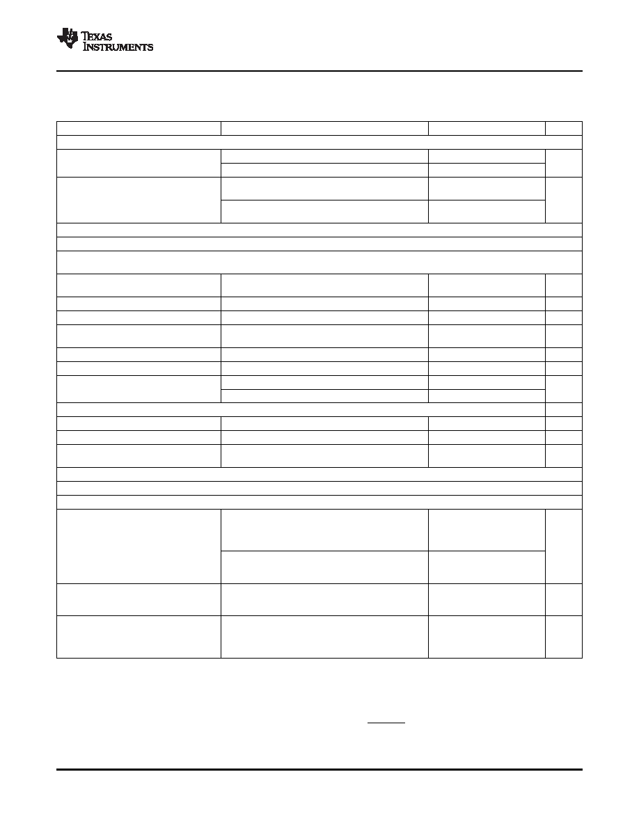
Electrical Characteristics (continued)
At 25
°C, AVDD, HVDD, IOVDD, TSVDD, = 3.3 V, SLVDD, SRVDD = 3.6V, DVDD = 1.8 V, VREF = 3.3 V, f
S (audio) =
48 kHz, CODEC_CLKIN = 256
× f
S, PLL = Off, SAR input is AUX1, VOL/MICDET pin disabled (unless otherwise noted)
PARAMETER
TEST CONDITIONS
MIN
TYP
MAX
UNIT
Microphone Bias
Page 1/register 46, bits D1–D0 = 10
2.25
2.5
2.75
Voltage output
V
Page 1/register 46, bits D1–D0 = 01
2
At 4-mA load current, page 1/register 46, bits D1–D0
5
= 10 (MICBIAS = 2.5 V)
Voltage regulation
mV
At 4-mA load current, page 1/register 46, bits D1–D0
7
= 01 (MICBIAS = 2 V)
Audio ADC Digital Decimation Filter Characteristics
See Section 5.5.4.4 for audio ADC decimation filter characteristics.
DAC HEADPHONE OUTPUT, AC-coupled load = 16
(single-ended),
driver gain = 0 dB, parasitic capacitance = 30 pF
Full-scale output voltage (0
Output common-mode setting = 1.65 V
0.707
Vrms
dB)
SNR
Signal-to-noise ratio
Measured as idle-channel noise, A-weighted(1)(2)
80
95
dB
THD
Total harmonic distortion
0-dBFS input
–85
–65
dB
Total harmonic distortion +
THD+N
0-dBFS input
–82
–60
dB
noise
Mute attenuation
87
dB
PSRR
Power-supply rejection ratio(3)
Ripple on HVDD (3.3 V) = 200 mVp-p at 1 kHz
62
dB
RL = 32 , THD+N ≤ –60 dB
20
PO
Maximum output power
mW
RL = 16 , THD+N ≤ –60 dB
60
DAC LINEOUT (HP Driver in Lineout Mode)
SNR
Signal-to-noise ratio
Measured as idle-channel noise, A-weighted
95
dB
THD
Total harmonic distortion
0-dBFS input, 0-dB gain
–86
dB
Total harmonic distortion +
THD+N
0-dBFS input, 0-dB gain
–82
dB
noise
DAC Digital Interpolation Filter Characteristics
See Section 5.6.1.4 for DAC interpolation filter characteristics.
DAC OUTPUT to CLASS-D SPEAKER OUTPUT; Load = 8
(differential), 50 pF
SLVDD = SRVDD = 3.6 V, BTL measurement, DAC
input = 0 dBFS, DAC VCM (page 1/register 31, bits
2.2
D4–D3) = 1.65 V, class-D gain = 6 dB,
THD
≤ –16.5 dB
Output voltage
Vrms
SLVDD = SRVDD = 3.6 V, BTL measurement, DAC
input = –2 dBFS, DAC VCM (page 1/register 31, bits
2.1
D4–D3) = 1.65 V, class-D gain = 6 dB, THD
≤ –20 dB
SLVDD = SRVDD = 3.6 V, BTL measurement, DAC
Output, common-mode
input = mute, DAC VCM (page 1/register 31, bits
1.65
V
D4–D3) = 1.65 V, class-D gain = 6 dB
SLVDD = SRVDD = 3.6 V, BTL measurement,
class-D gain = 6 dB, measured as idle-channel noise,
SNR
Signal-to-noise ratio
87
dB
A-weighted (with respect to full-scale output value of
2.2 Vrms)(1)(2)
(1)
Ratio of output level with 1-kHz full-scale sine-wave input, to the output level with the inputs short-circuited, measured A-weighted over a
20-Hz to 20-kHz bandwidth using an audio analyzer.
(2)
All performance measurements done with 20-kHz low-pass filter and, where noted, A-weighted filter. Failure to use such a filter may
result in higher THD+N and lower SNR and dynamic range readings than shown in the Electrical Characteristics. The low-pass filter
removes out-of-band noise, which, although not audible, may affect dynamic specification values.
ELECTRICAL SPECIFICATIONS
9
相關(guān)PDF資料 |
PDF描述 |
|---|---|
| TSC2300IPAGG4 | SPECIALTY CONSUMER CIRCUIT, PQFP64 |
| TSC2300IPAGR | SPECIALTY CONSUMER CIRCUIT, PQFP64 |
| TSC2300IPAG | SPECIALTY CONSUMER CIRCUIT, PQFP64 |
| TSC2300IPAGRG4 | SPECIALTY CONSUMER CIRCUIT, PQFP64 |
| TSC2301IPAGR | SPECIALTY CONSUMER CIRCUIT, PQFP64 |
相關(guān)代理商/技術(shù)參數(shù) |
參數(shù)描述 |
|---|---|
| TSC2117IRGZT | 制造商:Texas Instruments 功能描述:Touch Screen Controller IC |
| TSC22 | 制造商:未知廠家 制造商全稱:未知廠家 功能描述:EURO TERMINAL BLOCKS |
| TSC2200 | 制造商:BB 制造商全稱:BB 功能描述:PDA ANALOG INTERFACE CIRCUIT |
| TSC2200EVM | 功能描述:觸摸傳感器開(kāi)發(fā)工具 Touch Screen Contr Eval Mod RoHS:否 制造商:Cypress Semiconductor 工具用于評(píng)估: 接口類型: 工作電壓: 最大工作溫度: |
| TSC2200IPW | 功能描述:觸摸屏轉(zhuǎn)換器和控制器 Prog 4-Wire w/12-Bit 125KHz ADC & Key Ifc RoHS:否 制造商:Microchip Technology 類型:Resistive Touch Controllers 輸入類型:3 Key 數(shù)據(jù)速率:140 SPS 分辨率:10 bit 接口類型:4-Wire, 5-Wire, 8-Wire, I2C, SPI 電源電壓:2.5 V to 5.25 V 電源電流:17 mA 工作溫度:- 40 C to + 85 C 封裝 / 箱體:SSOP-20 |
發(fā)布緊急采購(gòu),3分鐘左右您將得到回復(fù)。