- 您現在的位置:買賣IC網 > PDF目錄98302 > TSC2117IRGZT (TEXAS INSTRUMENTS INC) SPECIALTY CONSUMER CIRCUIT, QCC48 PDF資料下載
參數資料
| 型號: | TSC2117IRGZT |
| 廠商: | TEXAS INSTRUMENTS INC |
| 元件分類: | 消費家電 |
| 英文描述: | SPECIALTY CONSUMER CIRCUIT, QCC48 |
| 封裝: | 7 X 7 MM, GREEN, PLASTIC, VQFN-48 |
| 文件頁數: | 143/192頁 |
| 文件大小: | 2728K |
| 代理商: | TSC2117IRGZT |
第1頁第2頁第3頁第4頁第5頁第6頁第7頁第8頁第9頁第10頁第11頁第12頁第13頁第14頁第15頁第16頁第17頁第18頁第19頁第20頁第21頁第22頁第23頁第24頁第25頁第26頁第27頁第28頁第29頁第30頁第31頁第32頁第33頁第34頁第35頁第36頁第37頁第38頁第39頁第40頁第41頁第42頁第43頁第44頁第45頁第46頁第47頁第48頁第49頁第50頁第51頁第52頁第53頁第54頁第55頁第56頁第57頁第58頁第59頁第60頁第61頁第62頁第63頁第64頁第65頁第66頁第67頁第68頁第69頁第70頁第71頁第72頁第73頁第74頁第75頁第76頁第77頁第78頁第79頁第80頁第81頁第82頁第83頁第84頁第85頁第86頁第87頁第88頁第89頁第90頁第91頁第92頁第93頁第94頁第95頁第96頁第97頁第98頁第99頁第100頁第101頁第102頁第103頁第104頁第105頁第106頁第107頁第108頁第109頁第110頁第111頁第112頁第113頁第114頁第115頁第116頁第117頁第118頁第119頁第120頁第121頁第122頁第123頁第124頁第125頁第126頁第127頁第128頁第129頁第130頁第131頁第132頁第133頁第134頁第135頁第136頁第137頁第138頁第139頁第140頁第141頁第142頁當前第143頁第144頁第145頁第146頁第147頁第148頁第149頁第150頁第151頁第152頁第153頁第154頁第155頁第156頁第157頁第158頁第159頁第160頁第161頁第162頁第163頁第164頁第165頁第166頁第167頁第168頁第169頁第170頁第171頁第172頁第173頁第174頁第175頁第176頁第177頁第178頁第179頁第180頁第181頁第182頁第183頁第184頁第185頁第186頁第187頁第188頁第189頁第190頁第191頁第192頁
DAC_L
DAC_R
24 dB to Mute
Digital
7- Bit ADC
AVDD
P1
AVSS
R1
R2
18 dB to Mute
24 dB to Mute
D-
DAC
S
D-
DAC
S
VolumeLevel
RegisterControlled
Vol
Ctl
Vol
Ctl
Programmable
DSP
Engine
B0210-05
VREF
IN
AVDD
C
VOL
ToneGeneratorandMixer Are
NOT Shown
VOL/
MICDET
Programmable
DSP
Engine
5.6.4
Dynamic Range Compression
TSC2117
Low-Power Audio Codec With Embedded miniDSP, Stereo Class-D
Speaker Amplifier, and Smart Four-Wire Touch-Screen Controller
SLAS550A – APRIL 2009 – REVISED JUNE 2009
www.ti.com
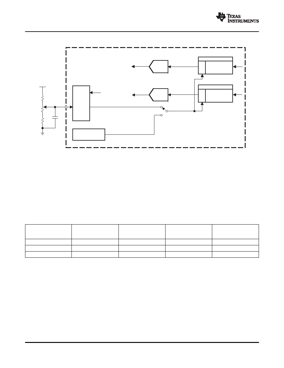
The VOL/MICDET pin connection and functionality are shown in Figure 5-33.
Figure 5-33. Digital Volume Controls for Beep Generator and DAC Play Data
As shown in Table 5-31, the VOL/MICDET pin has a range of volume control from 18 dB down to –63 dB,
and mute. However, if less maximum gain is required, then a smaller range of voltage should be applied
to the VOL/MICDET pin. This can be done by increasing the value of R2 relative to the value of (P1 + R1),
so that more voltage is available at the bottom of P1. The circuit should also be designed such that for the
values of R1, R2, and P1 chosen, the maximum voltage (top of the potentiometer) does not exceed
AVDD/2 (see Figure 5-33). The recommended values for R1, R2, and P1 for several maximum gains are
shown in Table 5-32. Note that In typical applications, R1 should not be 0
, as the VOL/MICDET pin
should not exceed AVDD/2 for proper ADC operation.
Table 5-32. VOL/MICDET Pin Gain Scaling
ADC VOLTAGE
R1
P1
R2
DIGITAL GAIN RANGE
for AVDD = 3.3 V
(k
)
(k
)
(k
)
(dB)
(V)
25
0
0 V to 1.65 V
18 dB to –63 dB
33
25
7.68
0.386 V to 1.642 V
3 dB to –63 dB
34.8
25
9.76
0.463 V to 1.649 V
0 dB to –63 dB
Typical music signals are characterized by crest factors, the ratio of peak signal power to average signal
power, of 12 dB or more. To avoid audible distortions due to clipping of peak signals, the gain of the DAC
channel must be adjusted so as not to cause hard clipping of peak signals. As a result, during nominal
periods, the applied gain is low, causing the perception that the signal is not loud enough. To overcome
this problem, DRC in the TSC2117 continuously monitors the output of the DAC digital volume control to
detect its power level relative to 0 dBFS. When the power level is low, DRC increases the input signal gain
to make it sound louder. At the same time, if a peaking signal is detected, it autonomously reduces the
applied gain to avoid hard clipping. This results in sounds more pleasing to the ear as well as sounding
louder during nominal periods.
The DRC functionality in the TSC2117 is implemented by a combination of processing blocks in the DAC
channel as described in Section 5.6.1.2.
APPLICATION INFORMATION
54
相關PDF資料 |
PDF描述 |
|---|---|
| TSC2300IPAGG4 | SPECIALTY CONSUMER CIRCUIT, PQFP64 |
| TSC2300IPAGR | SPECIALTY CONSUMER CIRCUIT, PQFP64 |
| TSC2300IPAG | SPECIALTY CONSUMER CIRCUIT, PQFP64 |
| TSC2300IPAGRG4 | SPECIALTY CONSUMER CIRCUIT, PQFP64 |
| TSC2301IPAGR | SPECIALTY CONSUMER CIRCUIT, PQFP64 |
相關代理商/技術參數 |
參數描述 |
|---|---|
| TSC2117IRGZT | 制造商:Texas Instruments 功能描述:Touch Screen Controller IC |
| TSC22 | 制造商:未知廠家 制造商全稱:未知廠家 功能描述:EURO TERMINAL BLOCKS |
| TSC2200 | 制造商:BB 制造商全稱:BB 功能描述:PDA ANALOG INTERFACE CIRCUIT |
| TSC2200EVM | 功能描述:觸摸傳感器開發(fā)工具 Touch Screen Contr Eval Mod RoHS:否 制造商:Cypress Semiconductor 工具用于評估: 接口類型: 工作電壓: 最大工作溫度: |
| TSC2200IPW | 功能描述:觸摸屏轉換器和控制器 Prog 4-Wire w/12-Bit 125KHz ADC & Key Ifc RoHS:否 制造商:Microchip Technology 類型:Resistive Touch Controllers 輸入類型:3 Key 數據速率:140 SPS 分辨率:10 bit 接口類型:4-Wire, 5-Wire, 8-Wire, I2C, SPI 電源電壓:2.5 V to 5.25 V 電源電流:17 mA 工作溫度:- 40 C to + 85 C 封裝 / 箱體:SSOP-20 |
發(fā)布緊急采購,3分鐘左右您將得到回復。