- 您現(xiàn)在的位置:買賣IC網(wǎng) > PDF目錄370028 > PXA270 (Intel Corp.) Electrical, Mechanical, and Thermal Specification PDF資料下載
參數(shù)資料
| 型號: | PXA270 |
| 廠商: | Intel Corp. |
| 英文描述: | Electrical, Mechanical, and Thermal Specification |
| 中文描述: | 電氣,機械和熱規(guī)格 |
| 文件頁數(shù): | 104/126頁 |
| 文件大?。?/td> | 1563K |
| 代理商: | PXA270 |
第1頁第2頁第3頁第4頁第5頁第6頁第7頁第8頁第9頁第10頁第11頁第12頁第13頁第14頁第15頁第16頁第17頁第18頁第19頁第20頁第21頁第22頁第23頁第24頁第25頁第26頁第27頁第28頁第29頁第30頁第31頁第32頁第33頁第34頁第35頁第36頁第37頁第38頁第39頁第40頁第41頁第42頁第43頁第44頁第45頁第46頁第47頁第48頁第49頁第50頁第51頁第52頁第53頁第54頁第55頁第56頁第57頁第58頁第59頁第60頁第61頁第62頁第63頁第64頁第65頁第66頁第67頁第68頁第69頁第70頁第71頁第72頁第73頁第74頁第75頁第76頁第77頁第78頁第79頁第80頁第81頁第82頁第83頁第84頁第85頁第86頁第87頁第88頁第89頁第90頁第91頁第92頁第93頁第94頁第95頁第96頁第97頁第98頁第99頁第100頁第101頁第102頁第103頁當(dāng)前第104頁第105頁第106頁第107頁第108頁第109頁第110頁第111頁第112頁第113頁第114頁第115頁第116頁第117頁第118頁第119頁第120頁第121頁第122頁第123頁第124頁第125頁第126頁
6-40
Electrical, Mechanical, and Thermal Specification
Intel PXA270 Processor
AC Timing Specifications
6.4.7
Expansion-Card Interface Parameters and Timing Diagrams
The following sections describe the read/write parameters and timing diagrams for CompactFlash*
and PC Card* (expansion card) memory interfaces with the memory controller.
Table 6-21
shows the timing parameters used in the timing diagrams,
Figure 6-26
and
Figure 6-27
.
Note:
Table 6-21
lists programmable register items. See the “Memory Controller” chapter in the
Intel
PXA27x Processor Family Developer’s Manual
for register configurations for more information on
these items.
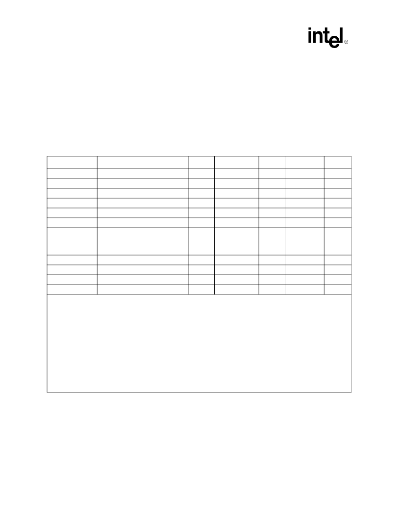
Table 6-21. Expansion-Card Interface AC Specifications
Symbols
Parameters
MIN
TYP
MAX
Units
Notes
tcdAVCL
Address Valid to CMD Low
2
MCx[SET]
127
CLK_MEM
1,2,3,4
tcdCHAI
CMD High to Address Invalid
0
MCx[HOLD]
63
CLK_MEM
1,2,3,5
tcdDVCL
Write Data Valid to CMD Low
—
1
—
CLK_MEM
1,3
tcdCHWDI
CMD High to Write Data Invalid
—
4
—
CLK_MEM
1,3
tcdDVCH
Read Data Valid to CMD High
2
—
—
CLK_MEM
1,3
tcdCHRDI
CMD High to Read Data Invalid
0
—
—
ns
3
tcdCMD
CMD Assert During Transfers
—
tcdCLPS +
tcdPHCH +
nPWAIT
assertion
—
CLK_MEM
1,3
tcdILCL
nIOIS16 Low to CMD Low
4
—
—
CLK_MEM
1,3
tcdCHIH
CMD High to nIOIS16 High
2
—
—
CLK_MEM
1,3
tcdCLPS
CMD Low to nPWAIT Sample
—
x_ASST_WAIT
—
CLK_MEM
1,3,6,7
tcdPHCH
nPWAIT High to CMD High
—
x_ASST_HOLD
—
CLK_MEM
1,3,6,8
NOTES:
1. All numbers shown are ideal, integer multiples of the CLK_MEM period. Actual numbers vary with pin-to-pin differences in
loading and transition direction (rise or fall).
2. Includes signals MA[25:0], nPREG, and nPSKTSEL.
3. CMD refers to signals nPWE, nPOE, nPIOW, and nPIOR
4. Refer to the
Intel PXA27x Processor Family Developer’s Manual
, Expansion Memory Timing Configuration registers to
change the assertion of CMD using the MCx[SET] bit fields.
5. Refer to the
Intel PXA27x Processor Family Developer’s Manual
, Expansion Memory Timing Configuration registers to
increase the assertion of CMD using the MCx[HOLD] bit fields.
6. Refer to the
Intel PXA27x Processor Family Developer’s Manual
, Expansion Memory Timing Configuration registers to
increase timings. The timings are changed by programming the MCx[ASST] respective bit fields. Refer to the PC Card
Interface Command Assertion Code table to see the effect of MCx[ASST].
7. tcdCLPS equals CLK_MEM * x_ASST_WAIT. Refer to the PC Card Interface Command Assertion Code table in the
Intel
PXA27x Processor Family Developer’s Manual
for the correlation between x_ASST_WAIT and the MCx[ASST] bit field.
8. tcdPHCH equals CLK_MEM * x_ASST_HOLD. Refer to the PC Card Interface Command Assertion Code table in the
Intel
PXA27x Processor Family Developer’s Manual
for the correlation between x_ASST_HOLD and the MCx[ASST] bit field.
相關(guān)PDF資料 |
PDF描述 |
|---|---|
| PXAC37 | XA 16-bit microcontroller family 32K/1024 OTP CAN transport layer controller 1 UART, 1 SPI Port, CAN 2.0B, 32 CAN ID Filters, transport layer co-proce |
| PXB16050U | NPN microwave power transistor |
| PY08-02 | INDUSTRIERELAIS FASSUNG PCB |
| PY08-02186697 | SOCKET PCB |
| PY14 | INDUSTRIERELAIS CHASSIS MONTAGESOCKEL |
相關(guān)代理商/技術(shù)參數(shù) |
參數(shù)描述 |
|---|---|
| PXA300 | 制造商:Marvell 功能描述: |
| PXA310 | 制造商:MARVELL 制造商全稱:MARVELL 功能描述:Rich Multimedia with Scalable Performance up to 624 MHz for Cost-Effective and Power-Effi cient Secure 3.5G Smartphones |
| PXA320 | 制造商:MARVELL 制造商全稱:MARVELL 功能描述:Cost-Effective, Scalable Performance up to 806 MHz for Power-Efficient, High-End Multimedia Handsets, Embedded Solutions, and Enterprise-Class Devices |
| PXA6.3VC101MF60TP | 功能描述:鋁有機聚合物電容器 100UF 6.3V SMT CAN RoHS:否 制造商:Panasonic Electronic Components 電容:470 uF 容差:20 % 電壓額定值:2.5 V ESR:4.5 mOhms 工作溫度范圍:- 40 C to + 105 C 端接類型:SMD/SMT 外殼直徑: 外殼長度:7.3 mm 外殼寬度:4.3 mm 外殼高度:1.9 mm 封裝:Reel |
| PXA6.3VC471MH12TP | 制造商:United Chemi-Con Inc 功能描述:Cap Aluminum 470uF 6.3V 20% (8 X 12mm) SMD 0.012 Ohm 4770mA 2000 hr 105°C T/R |
發(fā)布緊急采購,3分鐘左右您將得到回復(fù)。