- 您現(xiàn)在的位置:買賣IC網(wǎng) > PDF目錄368020 > PI7C7300 (Pericom Semiconductor Corp.) 3-PORT PCI-to-PCI BRIDGE PDF資料下載
參數(shù)資料
| 型號(hào): | PI7C7300 |
| 廠商: | Pericom Semiconductor Corp. |
| 英文描述: | 3-PORT PCI-to-PCI BRIDGE |
| 中文描述: | 3端口PCI至PCI橋 |
| 文件頁(yè)數(shù): | 16/109頁(yè) |
| 文件大?。?/td> | 779K |
| 代理商: | PI7C7300 |
第1頁(yè)第2頁(yè)第3頁(yè)第4頁(yè)第5頁(yè)第6頁(yè)第7頁(yè)第8頁(yè)第9頁(yè)第10頁(yè)第11頁(yè)第12頁(yè)第13頁(yè)第14頁(yè)第15頁(yè)當(dāng)前第16頁(yè)第17頁(yè)第18頁(yè)第19頁(yè)第20頁(yè)第21頁(yè)第22頁(yè)第23頁(yè)第24頁(yè)第25頁(yè)第26頁(yè)第27頁(yè)第28頁(yè)第29頁(yè)第30頁(yè)第31頁(yè)第32頁(yè)第33頁(yè)第34頁(yè)第35頁(yè)第36頁(yè)第37頁(yè)第38頁(yè)第39頁(yè)第40頁(yè)第41頁(yè)第42頁(yè)第43頁(yè)第44頁(yè)第45頁(yè)第46頁(yè)第47頁(yè)第48頁(yè)第49頁(yè)第50頁(yè)第51頁(yè)第52頁(yè)第53頁(yè)第54頁(yè)第55頁(yè)第56頁(yè)第57頁(yè)第58頁(yè)第59頁(yè)第60頁(yè)第61頁(yè)第62頁(yè)第63頁(yè)第64頁(yè)第65頁(yè)第66頁(yè)第67頁(yè)第68頁(yè)第69頁(yè)第70頁(yè)第71頁(yè)第72頁(yè)第73頁(yè)第74頁(yè)第75頁(yè)第76頁(yè)第77頁(yè)第78頁(yè)第79頁(yè)第80頁(yè)第81頁(yè)第82頁(yè)第83頁(yè)第84頁(yè)第85頁(yè)第86頁(yè)第87頁(yè)第88頁(yè)第89頁(yè)第90頁(yè)第91頁(yè)第92頁(yè)第93頁(yè)第94頁(yè)第95頁(yè)第96頁(yè)第97頁(yè)第98頁(yè)第99頁(yè)第100頁(yè)第101頁(yè)第102頁(yè)第103頁(yè)第104頁(yè)第105頁(yè)第106頁(yè)第107頁(yè)第108頁(yè)第109頁(yè)
PI7C7300A
3-PORT PCI-TO-PCI BRIDGE
ADVANCE INFORMATION
Page 16 OF 109
09/25/03 Revision 1.09
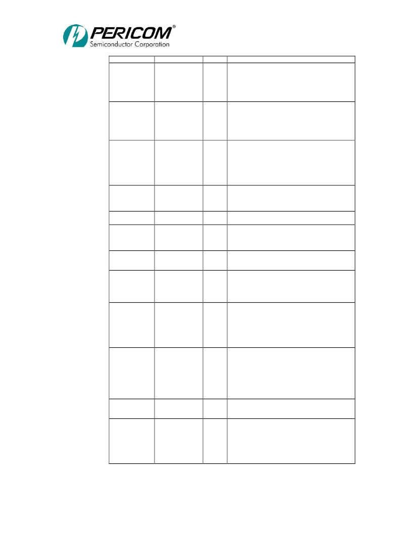
Name
S1_IRDY#,
S2_IRDY#
Pin #
H19,
B2
Type
PSTS
Description
Secondary IRDY (Active LOW).
Driven by the
initiator of a transaction to indicate its ability to
complete current data phase on the secondary side.
Once asserted in a data phase, it is not de-asserted until
the end of the data phase. Before tri-stated, it is driven
to a de-asserted state for one cycle.
Secondary TRDY (Active LOW).
Driven by the
target of a transaction to indicate its ability to complete
current data phase on the secondary side. Once
asserted in a data phase, it is not de-asserted until the
end of the data phase. Before tri-stated, it is driven to a
de-asserted state for one cycle.
Secondary Device Select (Active LOW).
Asserted by
the target indicating that the device is accepting the
transaction. As a master, PI7C7300A waits for the
assertion of this signal within 5 cycles of S1_FRAME#
or S2_FRAME# assertion; otherwise, terminate with
master abort. Before tri-stated, it is driven to a de-
asserted state for one cycle.
Secondary STOP (Active LOW).
Asserted by the
target indicating that the target is requesting the
initiator to stop the current transaction. Before tri-
stated, it is driven to a de-asserted state for one cycle.
Secondary LOCK (Active LOW).
Asserted by the
master for multiple transactions to complete.
Secondary Parity Error (Active LOW).
Asserted
when a data parity error is detected for data received on
the secondary interface. Before being tri-stated, it is
driven to a de-asserted state for one cycle.
Secondary System Error (Active LOW).
Can be
driven LOW by any device to indicate a system error
condition.
Secondary Request (Active LOW).
This is asserted
by an external device to indicate that it wants to start a
transaction on the secondary bus. The input is
externally pulled up through a resistor to VDD.
S1_TRDY#,
S2_TRDY#
H18,
A2
PSTS
S1_DEVSEL#,
S2_DEVSEL#
J20,
D3
PSTS
S1_STOP#,
S2_STOP#
J19,
C3
PSTS
S1_LOCK#,
S2_LOCK#
S1_PERR#,
S2_PERR#
J18,
B3
J17,
D4
PSTS
PSTS
S1_SERR#,
S2_SERR#
K20,
C4
PI
S1_REQ#[7:0],
S2_REQ#[6:0]
B11, A12, D13,
C13, C15, A16,
C17, B17
R3, P2, P1, M2,
M1, K1, K3
C11, B12, B13,
A14, D14, B16,
D16, B18
P4, R1, N4, M3,
L4, L1, K2
PIU
S1_GNT#[7:0]
S2_GNT#[6:0]
PO
Secondary Grant (Active LOW).
PI7C7300A asserts
this pin to access the secondary bus. PI7C7300A de-
asserts this pin for at least 2 PCI clock cycles before
asserting it again. During idle and S1_GNT# or S2-
GNT# asserted, PI7C7300A will drive S1_AD,
S1_CBE, and S1_PAR or S2_AD, S2_CBE, and
S2_PAR.
Secondary RESET (Active LOW).
Asserted when
any of the following conditions are met:
1.
Signal P_RESET# is asserted.
2.
Secondary reset bit in bridge control register in
configuration space is set.
When asserted, all control signals are tri-stated and
zeroes are driven on S1_AD, S1_CBE, and S1_PAR or
S2_AD, S2_CBE, and S2_PAR.
Secondary Enable (Active HIGH).
When S1_EN or
S2_EN is inactive, secondary bus PCI S1 or PCI S2
will be asynchronously tri-stated.
Secondary Interface 66MHz Operation.
This input
is used to specify if PI7C7300A is capable of running
at 66MHz on the secondary side. When HIGH, the S1
or S2 bus may run at 66MHz. When LOW, the S1 or
S2 bus may only run at 33MHz.
If P_M66EN is pulled LOW, both S1_M66EN and
S2_M66EN need to be LOW.
S1_RESET#,
S2_RESET#
B10,
T4
PO
S1_EN,
S2_EN
W3,
W4
PIU
S1_M66EN,
S2_M66EN
D7,
W5
PI
相關(guān)PDF資料 |
PDF描述 |
|---|---|
| PI7C7300A | 3-PORT PCI-to-PCI BRIDGE |
| PI7C7300ANA | 3-PORT PCI-to-PCI BRIDGE |
| PI7C8140A | 2 PORT PCI TO PCI BRIDGE PLX PCI 6140 COMPARISON |
| PI7C8148B | 2-PORT PCI-to-PCI BRIDGE PLX PC16152 COMPARISON |
| PI7C8150B-33 | PCI Bridge | Asynchronous 2-Port PCI Bridge |
相關(guān)代理商/技術(shù)參數(shù) |
參數(shù)描述 |
|---|---|
| PI7C7300A | 制造商:PERICOM 制造商全稱:Pericom Semiconductor Corporation 功能描述:3-PORT PCI-to-PCI BRIDGE |
| PI7C7300AEVB-3 | 功能描述:界面開(kāi)發(fā)工具 3 Port PCI Bridge Eval Brd RoHS:否 制造商:Bourns 產(chǎn)品:Evaluation Boards 類型:RS-485 工具用于評(píng)估:ADM3485E 接口類型:RS-485 工作電源電壓:3.3 V |
| PI7C7300ANA | 制造商:Pericom Semiconductor Corporation 功能描述:PCI-to-PCI Bridge 272-Pin BGA 制造商:Pericom Semiconductor Corporation 功能描述:PCI to PCI Bridge 272-Pin BGA |
| PI7C7300ANAE | 功能描述:外圍驅(qū)動(dòng)器與原件 - PCI 3 Port PCI Bridge RoHS:否 制造商:PLX Technology 工作電源電壓: 最大工作溫度: 安裝風(fēng)格:SMD/SMT 封裝 / 箱體:FCBGA-1156 封裝:Tray |
| PI7C7300ANA-E | 制造商:Pericom Semiconductor Corporation 功能描述:PCI-to-PCI Bridge 272-Pin BGA 制造商:Pericom Semiconductor Corporation 功能描述:PCI to PCI Bridge 272-Pin BGA |
發(fā)布緊急采購(gòu),3分鐘左右您將得到回復(fù)。