- 您現(xiàn)在的位置:買賣IC網(wǎng) > PDF目錄371014 > MC145230 (Motorola, Inc.) Dual PLL Frequency Synthesizers With DACs and Voltage Multipliers(帶DACs和電壓乘法器的雙PLL頻率合成器) PDF資料下載
參數(shù)資料
| 型號: | MC145230 |
| 廠商: | Motorola, Inc. |
| 英文描述: | Dual PLL Frequency Synthesizers With DACs and Voltage Multipliers(帶DACs和電壓乘法器的雙PLL頻率合成器) |
| 中文描述: | 雙鎖相環(huán)頻率合成器與DAC和電壓倍增器(帶數(shù)模轉(zhuǎn)換器和電壓乘法器的雙鎖相環(huán)頻率合成器) |
| 文件頁數(shù): | 30/71頁 |
| 文件大?。?/td> | 906K |
| 代理商: | MC145230 |
第1頁第2頁第3頁第4頁第5頁第6頁第7頁第8頁第9頁第10頁第11頁第12頁第13頁第14頁第15頁第16頁第17頁第18頁第19頁第20頁第21頁第22頁第23頁第24頁第25頁第26頁第27頁第28頁第29頁當(dāng)前第30頁第31頁第32頁第33頁第34頁第35頁第36頁第37頁第38頁第39頁第40頁第41頁第42頁第43頁第44頁第45頁第46頁第47頁第48頁第49頁第50頁第51頁第52頁第53頁第54頁第55頁第56頁第57頁第58頁第59頁第60頁第61頁第62頁第63頁第64頁第65頁第66頁第67頁第68頁第69頁第70頁第71頁

MC145225 MC145230
30
MOTOROLA RF/IF DEVICE DATA
2
1
2
1
2
1
Rs
Ls
Cs
Re
Xe
Co
X1
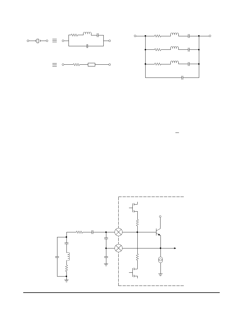
Figure 23. Crystal Resonator Equivalent Circuit
NOTE: Values are supplied by crystal manufacturer (parallel
resonant crystal).
Figure 24. Overtone Crystal Equivalent Circuit
2
1
L1s
C1s
R1s
Co
L3s
C3s
R3s
L5s
C5s
R5s
Because of the acoustic properties of the crystal
resonator, the crystal “tank” responds to energy not only at its
fundamental frequency, but also at specific multiples of the
fundamental frequency. In the same manner that a shorted or
open transmission line responds to multiples of the
fundamental frequency, the crystal “tank” responds similarly.
A shorted half–wave transmission line (or closed acoustic
chamber) will not only resonate at its fundamental frequency,
but also at odd multiples of the fundamental. These are called
the overtones of the crystal and represent frequencies at
which the crystal can be made to oscillate. The equivalent
circuit of an overtone crystal is shown is Figure 24.
The components for the appropriate overtone are
represented by 1, 3, and 5. The fundamental components are
represented by 1, and those of importance for the third and
fifth overtones, by 3 and 5.
Fundamental Mode
The equivalent circuit for the Colpitts oscillator operating in
the fundamental mode is shown in Figure 25.
C3 is selected to provide a small reduction in the inductive
property of the crystal. In this manner, the frequency of the
oscillator can be “pulled” slightly. The biasing combination of
M1R1 and M2R2 provide the ability to start operation with a
higher than normal operating current to stimulate crystal
activity. This “kick start” current is nominally four times the
normal current. An internal counter times the application of
the “kick start” and returns the current to normal after the time
out period.
The mutual conductance (transconductance) of the
transistor Q1 is useful in determining the conditions
necessary for oscillation. The nominal value for the
transconductance is found from the formula
Ie
26
gm =
where Ie is the emitter current in mA.
The operation of the oscillator can be described using the
concept of “negative resistance”. In a normal tuned circuit,
any excitation tends to be dissipated by the resistance of the
circuit and oscillation dies out. The resistive part of the crystal
along with the resistance of the wiring and the internal
resistance of C1, C2, and C3, make up this “damping”
resistance. Some form of energy must be fed back into the
circuit to sustain oscillation. This is the purpose of the
amplifier.
Figure 25. Fundamental Mode Colpitts Oscillator Equivalent Circuit
C3
C2
C1
R1
R2
Q1
M1
+V
Oscb
Osce
Frequency Synthesizer
I1
200/800
μ
A
R1s
Co
C1s
Rst
M2
L1s
0
0
0
相關(guān)PDF資料 |
PDF描述 |
|---|---|
| MC14528BCL | Dual Monostable Multivibrator |
| MC14528 | DEFLECTION PROCESSOR FOR MULTISYNC MONITORS |
| MC14528 | Dual Monostable Multivibrator |
| MC14528BFEL | Dual Monostable Multivibrator |
| MC14528BCP | Dual Monostable Multivibrator |
相關(guān)代理商/技術(shù)參數(shù) |
參數(shù)描述 |
|---|---|
| MC14526B AC7 WAF | 制造商:ON Semiconductor 功能描述: |
| MC14526BAC7 WAF | 制造商:ON Semiconductor 功能描述: |
| MC14526BCL | 制造商: 功能描述: 制造商:undefined 功能描述: |
| MC14526BCP | 功能描述:計(jì)數(shù)器移位寄存器 3-18V Presettable RoHS:否 制造商:Texas Instruments 計(jì)數(shù)器類型: 計(jì)數(shù)順序:Serial to Serial/Parallel 電路數(shù)量:1 封裝 / 箱體:SOIC-20 Wide 邏輯系列: 邏輯類型: 輸入線路數(shù)量:1 輸出類型:Open Drain 傳播延遲時(shí)間:650 ns 最大工作溫度:+ 125 C 最小工作溫度:- 40 C 封裝:Reel |
| MC14526BCPG | 功能描述:計(jì)數(shù)器移位寄存器 3-18V Presettable 4-Bit Down RoHS:否 制造商:Texas Instruments 計(jì)數(shù)器類型: 計(jì)數(shù)順序:Serial to Serial/Parallel 電路數(shù)量:1 封裝 / 箱體:SOIC-20 Wide 邏輯系列: 邏輯類型: 輸入線路數(shù)量:1 輸出類型:Open Drain 傳播延遲時(shí)間:650 ns 最大工作溫度:+ 125 C 最小工作溫度:- 40 C 封裝:Reel |
發(fā)布緊急采購,3分鐘左右您將得到回復(fù)。