- 您現(xiàn)在的位置:買賣IC網(wǎng) > PDF目錄373367 > SC1200 (Texas Instruments, Inc.) Precision Analog-to-Digital Converter (ADC) and Digital-to-Analog Converter (DAC) with 8051 Microcontroller and Flash Memory PDF資料下載
參數(shù)資料
| 型號: | SC1200 |
| 廠商: | Texas Instruments, Inc. |
| 英文描述: | Precision Analog-to-Digital Converter (ADC) and Digital-to-Analog Converter (DAC) with 8051 Microcontroller and Flash Memory |
| 中文描述: | 精密模擬到數(shù)字轉(zhuǎn)換器(ADC)和數(shù)字到模擬轉(zhuǎn)換器(DAC)的8051微控制器和閃存 |
| 文件頁數(shù): | 33/60頁 |
| 文件大小: | 802K |
| 代理商: | SC1200 |
第1頁第2頁第3頁第4頁第5頁第6頁第7頁第8頁第9頁第10頁第11頁第12頁第13頁第14頁第15頁第16頁第17頁第18頁第19頁第20頁第21頁第22頁第23頁第24頁第25頁第26頁第27頁第28頁第29頁第30頁第31頁第32頁當(dāng)前第33頁第34頁第35頁第36頁第37頁第38頁第39頁第40頁第41頁第42頁第43頁第44頁第45頁第46頁第47頁第48頁第49頁第50頁第51頁第52頁第53頁第54頁第55頁第56頁第57頁第58頁第59頁第60頁

MSC1200
SBAS289E
33
www.ti.com
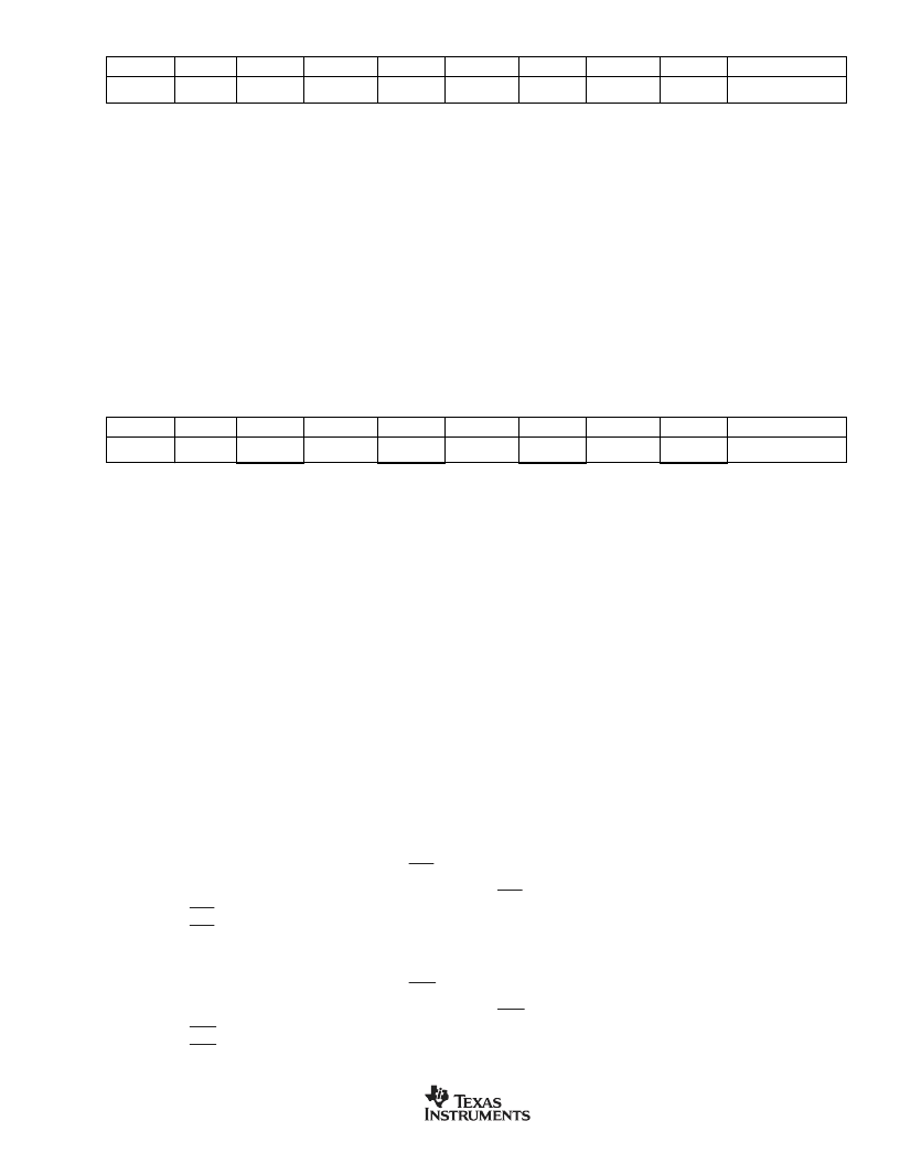
SMOD
bit 7
Serial Port 0 Baud Rate Doubler Enable.
The serial baud rate doubling function for Serial Port 0.
0: Serial Port 0 baud rate will be a standard baud rate.
1: Serial Port 0 baud rate will be double that defined by baud rate generation equation.
GF1
bit 3
General-Purpose User Flag 1.
This is a general-purpose flag for software control.
GF0
bit 2
General-Purpose User Flag 0.
This is a general-purpose flag for software control.
STOP
bit 1
Stop Mode Select.
Setting this bit will halt the oscillator and block external clocks. This bit will always read as a 0.
Exit with RESET. In this mode, internal peripherals are frozen and I/O pins are held in their current state. The ADC
is frozen, but IDAC and VREF remain active.
IDLE
bit 0
Idle Mode Select.
Setting this bit will freeze the CPU, Timer 0 and 1, and the USART; other peripherals remain
active. This bit will always be read as a 0. Exit with AIE (A6
H
) and EWU (C6
H
) interrupts (refer to Figure 4 for clocks
affected during IDLE).
Timer/Counter Control (TCON)
7
6
5
4
3
2
1
0
Reset Value
SFR 87
H
SMOD
0
1
1
GF1
GF0
STOP
IDLE
30
H
TF1
bit 7
Timer 1 Overflow Flag.
This bit indicates when Timer 1 overflows its maximum count as defined by the current
mode. This bit can be cleared by software and is automatically cleared when the CPU vectors to the Timer 1
interrupt service routine.
0: No Timer 1 overflow has been detected.
1: Timer 1 has overflowed its maximum count.
TR1
Timer 1 Run Control.
This bit enables/disables the operation of Timer 1. Halting this timer will preserve the
current bit 6 count in TH1, TL1.
0: Timer is halted.
1: Timer is enabled.
TF0
bit 5
Timer 0 Overflow Flag.
This bit indicates when Timer 0 overflows its maximum count as defined by the current
mode. This bit can be cleared by software and is automatically cleared when the CPU vectors to the Timer 0
interrupt service routine.
0: No Timer 0 overflow has been detected.
1: Timer 0 has overflowed its maximum count.
TR0
bit 4
Timer 0 Run Control.
This bit enables/disables the operation of Timer 0. Halting this timer will preserve the
current count in TH0, TL0.
0: Timer is halted.
1: Timer is enabled.
IE1
bit 3
Interrupt 1 Edge Detect.
This bit is set when an edge/level of the type defined by IT1 is detected. If IT1 = 1, this
bit will remain set until cleared in software or the start of the External Interrupt 1 service routine. If IT1 = 0, this
bit will inversely reflect the state of the
INT1
pin.
IT1
bit 2
Interrupt 1 Type Select.
This bit selects whether the
INT1
pin will detect edge or level triggered interrupts.
0:
INT1
is level triggered.
1:
INT1
is edge triggered.
Interrupt 0 Edge Detect.
This bit is set when an edge/level of the type defined by IT0 is detected. If IT0 = 1, this
bit will remain set until cleared in software or the start of the External Interrupt 0 service routine. If IT0 = 0, this
bit will inversely reflect the state of the
INT0
pin.
IE0
bit 3
IT0
bit 2
Interrupt 0 Type Select.
This bit selects whether the
INT0
pin will detect edge or level triggered interrupts.
0:
INT0
is level triggered.
1:
INT0
is edge triggered.
Power Control (PCON)
7
6
5
4
3
2
1
0
Reset Value
SFR 88
H
TF1
TR1
TF0
TR0
IE1
IT1
IE0
IT0
00
H
相關(guān)PDF資料 |
PDF描述 |
|---|---|
| SC141E | 6-A AND 10-A SILICON TRIACS |
| SC146B | 6-A AND 10-A SILICON TRIACS |
| SC141B | 6-A AND 10-A SILICON TRIACS |
| SC141D | 6-A AND 10-A SILICON TRIACS |
| SC141M | 6-A AND 10-A SILICON TRIACS |
相關(guān)代理商/技術(shù)參數(shù) |
參數(shù)描述 |
|---|---|
| SC12-00 | 制造商: 功能描述: 制造商:undefined 功能描述: |
| SC1-200/5A | 制造商:TE Connectivity 功能描述:CURRENT TRANSFORMER CASE SIZE 1 SPLIT CORE 200/5 AMPS AC 1.5VA-CL1 2.5VA-CL3 |
| SC1200/KR32A | 制造商:X-10 Pro 功能描述:Personal Assistance Voice Dialer |
| SC12004 | 制造商:Ferraz Shawmut 功能描述: |
| SC1200UCL-266 | 制造商:Rochester Electronics LLC 功能描述: |
發(fā)布緊急采購,3分鐘左右您將得到回復(fù)。