- 您現(xiàn)在的位置:買賣IC網(wǎng) > PDF目錄369993 > pentium processor (Intel Corp.) 32 Bit Processor With MMX And Mobile Module(32位帶移動模塊和MMX技術CPU) PDF資料下載
參數(shù)資料
| 型號: | pentium processor |
| 廠商: | Intel Corp. |
| 英文描述: | 32 Bit Processor With MMX And Mobile Module(32位帶移動模塊和MMX技術CPU) |
| 中文描述: | 32位處理器MMX和移動模塊(32位帶移動模塊和MMX公司技術的CPU) |
| 文件頁數(shù): | 30/35頁 |
| 文件大小: | 550K |
| 代理商: | PENTIUM PROCESSOR |
第1頁第2頁第3頁第4頁第5頁第6頁第7頁第8頁第9頁第10頁第11頁第12頁第13頁第14頁第15頁第16頁第17頁第18頁第19頁第20頁第21頁第22頁第23頁第24頁第25頁第26頁第27頁第28頁第29頁當前第30頁第31頁第32頁第33頁第34頁第35頁

INTEL PENTIUM PROCESSOR WITH MMX TECHNOLOGY MOBILE MODULE
E
30
9/19/97 1:03 PM SPEIDEN_.DOC
4.1.2.
THICKNESS
PRINTED CIRCUIT BOARD
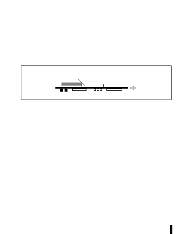
Figure 7 shows the Intel Mobile Module profile and
the associated minimum and maximum thickness
of the printed circuit board (PCB). The range of
PCB
thickness
allows
for
different
PCB
technologies to be used with current and future
modules.
NOTE
The system manufacturer must ensure that
the mechanical restraining method and/or
system-level EMI contacts are able to
support this range of PCB thickness, to
ensure compatibility with future modules.
Intel Mobile Module
printed circuit board
.070" maximum
.057" minimum
Figure 7. PCB Board Thickness
4.1.3.
HEIGHT RESTRICTIONS
Figure 8 shows the Intel Mobile Module
mechanical stackup and associated component
clearance requirements. This "block" represents
the volume that may be occupied by components
on the various versions of the processor module.
The OEM system should be defined so that no part
of the system will intrude into this volume, which
may result in part-to-part interference.
The system manufacturer establishes the board-
to-board clearance between the Intel Mobile
Module and the I/O Module by selecting one of
three possible mating connectors. The mating
connectors provide board-to-board clearance
distances of 4 mm, 6 mm or 8 mm. With these
three options, the system manufacturer has
reasonable flexibility in choosing components on
the I/O Module that are between the two boards.
NOTE
The Intel Mobile Module top side component
clearance is referenced from the bottom of the
PCB, so it is independent of the PCB thickness.
Figure 8 shows the module volume assuming a
4mm board-to-board connector. When using the
4mm connector, 2mm of the connector height
extends beyond the module volume shown in
figure 8. If the 6mm board-to-board connector is
used on the I/O module, then 4mm extends
beyond the module
“keep-out” volume. If using the
8mm connector, 6mm will extend beyond the
module “keep-out” volume.
相關PDF資料 |
PDF描述 |
|---|---|
| PESD0603-140 | Raychem Overvoltage Devices |
| PESD5V2S18U | ESD protection array |
| PESDXL4UW | Low capacitance quadruple ESD protection array |
| PESDXL4UG | Low capacitance quadruple ESD protection diode array in SOT353 package |
| PESDXU1UT | Ultra low capacitance ESD protection diode in SOT23 package |
相關代理商/技術參數(shù) |
參數(shù)描述 |
|---|---|
| P-ENV568K3G3 | 制造商:Panasonic Industrial Company 功能描述:TUNER |
| PEO14012 | 制造商:TE Connectivity 功能描述:RELAY SPCO 12VDC |
| PEO14024 | 制造商:TE Connectivity 功能描述:RELAY SPCO 24VDC |
| PEO96742 | 制造商:Delphi Corporation 功能描述:ASM TERM |
| PEOODO3A | 制造商:MACOM 制造商全稱:Tyco Electronics 功能描述:Versatile Power Entry Module with Small Footprint |
發(fā)布緊急采購,3分鐘左右您將得到回復。