- 您現(xiàn)在的位置:買賣IC網(wǎng) > PDF目錄369993 > pentium pro processor (Intel Corp.) Pentium Pro Processor with 1MB L2 Cache at 200MHZ(1兆比特L2高速緩存頻率200兆赫茲處理器) PDF資料下載
參數(shù)資料
| 型號: | pentium pro processor |
| 廠商: | Intel Corp. |
| 英文描述: | Pentium Pro Processor with 1MB L2 Cache at 200MHZ(1兆比特L2高速緩存頻率200兆赫茲處理器) |
| 中文描述: | 奔騰Pro處理器在200MHz(1兆比特二級高速緩存頻率200兆赫茲處理器帶有1MB的L2緩存) |
| 文件頁數(shù): | 20/39頁 |
| 文件大?。?/td> | 930K |
| 代理商: | PENTIUM PRO PROCESSOR |
第1頁第2頁第3頁第4頁第5頁第6頁第7頁第8頁第9頁第10頁第11頁第12頁第13頁第14頁第15頁第16頁第17頁第18頁第19頁當(dāng)前第20頁第21頁第22頁第23頁第24頁第25頁第26頁第27頁第28頁第29頁第30頁第31頁第32頁第33頁第34頁第35頁第36頁第37頁第38頁第39頁
AP-523
E
20
Another useful formula for estimating the amount of bulk
capacitance required is shown in Equation 3. This
ignores the ESR of the component but furnishes the
amount of capacitance that would be required from an
ideal component.
Equation 3. Capacitance for an Ideal Capacitor
C
I
v
t
=
D
I
represents the current that the bulk capacitance must
be able to deliver or sink. This is equal to the difference
between high and low current states since the power
supply will initially continue to supply the same current
that it had been prior to the load change.
D
v
is the
allowable voltage change budgeted for bulk capacitive
sag (discharge) over the period
D
t.
D
t
is the reaction time
of the power source.
Assuming some representative numbers for
I
,
D
V
, and
D
t
,
the capacitance required is shown by Equation 4.
Equation 4. Capacitance needed if ESR is 0 ohms
C
A
V
x
s
F
=
=
85
.
0 060
.
30 10
4250
6
μ
Combining the above formulas to remove the resistive
drop from the budget for the bulk capacitance gives
Equation 5.
Equation 5. Capacitance vs. ESR
C
I
×
t
V
I
ESR
=
×
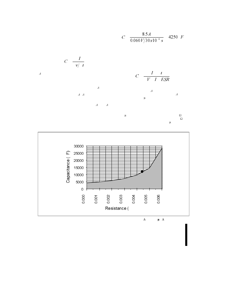
This equation leads to the capacitance vs. ESR graph
shown in Figure 19, when
D
V
is assumed to be 60 mV,
I
is assumed to be 8.5A, and the reaction time (
D
t
) of the
power source is 30
m
s. The shaded area of the graph
covers capacitance types that are insufficient for this
application. Again this provides a figure that can be used
to get a feel for the type of capacitors required. For
example, to satisfy this equation one could use twelve
1000
m
F capacitors if the ESR of each was 53 m
W
. The
parallel resistance of 12 capacitors would be 4.4 m
W
and
the parallel capacitance would be 12,000
m
F, which falls
in the white zone of the graph in Figure 19.
0
5000
10000
15000
20000
25000
30000
0.000
0.001
0.002
0.003
0.004
0.005
0.006
Resistance (
)
Capacitance (
F)
Figure 19. Capacitance Required vs. ESR at 8.5A, 60 mV
D
V and 30
m
s
D
t
相關(guān)PDF資料 |
PDF描述 |
|---|---|
| pentium processor with MMX | 32-bit processor with MMX technology(32位帶MMX技術(shù)處理器) |
| pentium processor | 32 Bit Processor With MMX And Mobile Module(32位帶移動模塊和MMX技術(shù)CPU) |
| PESD0603-140 | Raychem Overvoltage Devices |
| PESD5V2S18U | ESD protection array |
| PESDXL4UW | Low capacitance quadruple ESD protection array |
相關(guān)代理商/技術(shù)參數(shù) |
參數(shù)描述 |
|---|---|
| P-ENV568K3G3 | 制造商:Panasonic Industrial Company 功能描述:TUNER |
| PEO14012 | 制造商:TE Connectivity 功能描述:RELAY SPCO 12VDC |
| PEO14024 | 制造商:TE Connectivity 功能描述:RELAY SPCO 24VDC |
| PEO96742 | 制造商:Delphi Corporation 功能描述:ASM TERM |
| PEOODO3A | 制造商:MACOM 制造商全稱:Tyco Electronics 功能描述:Versatile Power Entry Module with Small Footprint |
發(fā)布緊急采購,3分鐘左右您將得到回復(fù)。