- 您現(xiàn)在的位置:買賣IC網(wǎng) > PDF目錄371014 > MC145225 (Motorola, Inc.) Dual PLL Frequency Synthesizers With DACs and Voltage Multipliers(帶DACs和電壓乘法器的雙PLL頻率合成器) PDF資料下載
參數(shù)資料
| 型號(hào): | MC145225 |
| 廠商: | Motorola, Inc. |
| 英文描述: | Dual PLL Frequency Synthesizers With DACs and Voltage Multipliers(帶DACs和電壓乘法器的雙PLL頻率合成器) |
| 中文描述: | 雙鎖相環(huán)頻率合成器與DAC和電壓倍增器(帶數(shù)模轉(zhuǎn)換器和電壓乘法器的雙鎖相環(huán)頻率合成器) |
| 文件頁(yè)數(shù): | 41/71頁(yè) |
| 文件大?。?/td> | 906K |
| 代理商: | MC145225 |
第1頁(yè)第2頁(yè)第3頁(yè)第4頁(yè)第5頁(yè)第6頁(yè)第7頁(yè)第8頁(yè)第9頁(yè)第10頁(yè)第11頁(yè)第12頁(yè)第13頁(yè)第14頁(yè)第15頁(yè)第16頁(yè)第17頁(yè)第18頁(yè)第19頁(yè)第20頁(yè)第21頁(yè)第22頁(yè)第23頁(yè)第24頁(yè)第25頁(yè)第26頁(yè)第27頁(yè)第28頁(yè)第29頁(yè)第30頁(yè)第31頁(yè)第32頁(yè)第33頁(yè)第34頁(yè)第35頁(yè)第36頁(yè)第37頁(yè)第38頁(yè)第39頁(yè)第40頁(yè)當(dāng)前第41頁(yè)第42頁(yè)第43頁(yè)第44頁(yè)第45頁(yè)第46頁(yè)第47頁(yè)第48頁(yè)第49頁(yè)第50頁(yè)第51頁(yè)第52頁(yè)第53頁(yè)第54頁(yè)第55頁(yè)第56頁(yè)第57頁(yè)第58頁(yè)第59頁(yè)第60頁(yè)第61頁(yè)第62頁(yè)第63頁(yè)第64頁(yè)第65頁(yè)第66頁(yè)第67頁(yè)第68頁(yè)第69頁(yè)第70頁(yè)第71頁(yè)

MC145225 MC145230
41
MOTOROLA RF/IF DEVICE DATA
7C. MAIN LOOP FILTER DESIGN — ADAPT
Introduction
For PSpice simulation, the schematic model shown in
Figure 41 was chosen. The classical PLL model employing a
phase–frequency detector, a VCO, and an adaptive loop filter
is used to simplify visualization of circuit operation. The
parameter tables allow for modification of circuit performance
by providing an easy method for altering critical values
without necessitating changes to sub–level schematics. The
definition for the terms are:
tw = 2
π
,
fr = reference frequency,
td = time delay; allows delay of the start of the high
current mode (used to perform reference spur
measurements),
CPL = charge pump low current,
CPH = charge pump high current,
N = N counter value,
Sz = amount the N counter is being increased (or
decreased) by,
St = number of fr cycles that CPH is active; this value
is either 16, 32, 64, or 128,
VCPHH = charge pump voltage – high,
VCPHL = charge pump voltage – low,
K1 = VCO gain (Hz/volt),
fc = VCO frequency at 0 V control voltage,
H = reference spur scaling factor.
Modeling the Phase–frequency Detector
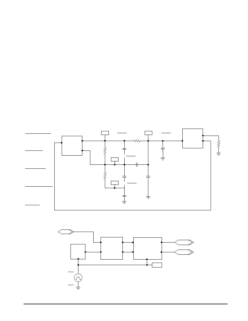
Figure 42 is a schematic of the phase–frequency detector.
It includes the reference oscillator model, phase–frequency
detector model, and charge pump models. V1 is the control
element used to generate the step time for switching between
CPL and CPH. The signal source VPULSE, is used to
simulate the timer that controls when CPL and CPH are
turned on. PW calculates the pulse width that simulates the
counter from the values for St and fr that are entered in the
parameter tables on the top level schematic.
Figure 41. Top Level PLL Model
50 p
PDout–Lo
In
HB2
C2
20 k
C5
C6
1 k
R10
ctrl
330 p
C4
Out
VCO
HB1
33 p
R3
Parameters:
tw
fr
H
Parameters:
N
Sz
St
6.283185308
25 k
1
Parameters:
CPL
CPH
K1
1 x 10⁻³
4 x 10⁻³
4 x 10⁶
29320
400
32
PDout–Hi
+
+
60.4 k
R1
C1
40.2 k
+
+
3300 p
10%
330 p
fr N – fc
C3
330 p
fr N – fc
R2
Parameters:
VCPHH
VCPHL
fc
5
0
727.6 x 10⁶
Parameters:
td
0
K1
IC =
fr N – fc
K1
IC =
fr N – fc
K1
IC =
K1
IC =
0
0
0
0
Figure 42. Phase–frequency Detector with Dual Charge Pumps
HB1
Shift
+
–
HB3
HB2
PDout–Lo
PDout–Hi
PDout–Hi
Shift
PDout–Lo
R
φ
V
φ
R
φ
V
φ
fin
Ref
Ref
Shift
V1
In
PW =4 fr
St
td =
fr
4 td
0
相關(guān)PDF資料 |
PDF描述 |
|---|---|
| MC145230 | Dual PLL Frequency Synthesizers With DACs and Voltage Multipliers(帶DACs和電壓乘法器的雙PLL頻率合成器) |
| MC14528BCL | Dual Monostable Multivibrator |
| MC14528 | DEFLECTION PROCESSOR FOR MULTISYNC MONITORS |
| MC14528 | Dual Monostable Multivibrator |
| MC14528BFEL | Dual Monostable Multivibrator |
相關(guān)代理商/技術(shù)參數(shù) |
參數(shù)描述 |
|---|---|
| MC14522BCP | 制造商:Motorola Inc 功能描述:Counter, Down, Decade, 16 Pin, Plastic, DIP |
| MC14522BDW | 制造商:Motorola Inc 功能描述: |
| MC14526B AC7 WAF | 制造商:ON Semiconductor 功能描述: |
| MC14526BAC7 WAF | 制造商:ON Semiconductor 功能描述: |
| MC14526BCL | 制造商: 功能描述: 制造商:undefined 功能描述: |
發(fā)布緊急采購(gòu),3分鐘左右您將得到回復(fù)。