- 您現(xiàn)在的位置:買賣IC網(wǎng) > PDF目錄369885 > LXT350PE PCM TRANSCEIVER|SINGLE|CEPT PCM-30/E-1|CMOS|LDCC|28PIN|PLASTIC PDF資料下載
參數(shù)資料
| 型號: | LXT350PE |
| 英文描述: | PCM TRANSCEIVER|SINGLE|CEPT PCM-30/E-1|CMOS|LDCC|28PIN|PLASTIC |
| 中文描述: | 的PCM收發(fā)器|單|優(yōu)稅PCM-30/E-1 |的CMOS | LDCC | 28腳|塑料 |
| 文件頁數(shù): | 24/50頁 |
| 文件大小: | 1197K |
| 代理商: | LXT350PE |
第1頁第2頁第3頁第4頁第5頁第6頁第7頁第8頁第9頁第10頁第11頁第12頁第13頁第14頁第15頁第16頁第17頁第18頁第19頁第20頁第21頁第22頁第23頁當(dāng)前第24頁第25頁第26頁第27頁第28頁第29頁第30頁第31頁第32頁第33頁第34頁第35頁第36頁第37頁第38頁第39頁第40頁第41頁第42頁第43頁第44頁第45頁第46頁第47頁第48頁第49頁第50頁

LXT350
—
T1/E1 Short Haul Transceiver with Crystal-less Jitter Attenuation
24
Datasheet
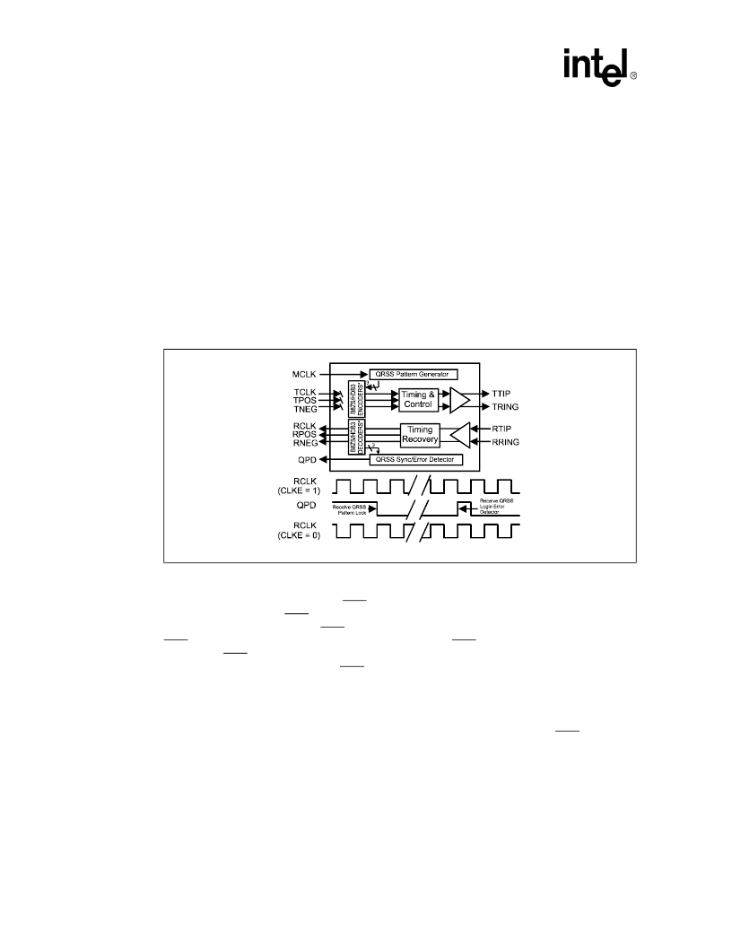
Both Hardware and Host Modes allow QRSS mode. The QRSS pattern is normally locked to
TCLK, however, if there is no TCLK, MCLK is the clock source. Bellcore Pub 62411 defines the
T1 QRSS transmit format and ITU G.703 defines the E1 format.
With QRSS transmission enabled, it is possible to insert a logic error into the transmit data stream
by causing a Low-to-High transition on the INSLER pin. However, if no logic or bit errors are to be
inserted into the QRSS pattern, INSLER must remain Low. Logic Error insertion waits until the
next bit if the current bit is
“
jammed
”
. When there are more than 14 consecutive 0s, the output is
jammed to a 1.
A Low-to-High transition on the INSBPV pin will insert a bipolar violation in the QRSS pattern.
Note that the BPV insertion occurs regardless of whether the device is in Bipolar or Unipolar
operating mode.
In Hardware mode, connecting the TAOS pin to Midrange enables QRSS transmission. In Host
mode, setting bits CR2.EPAT0 = 0 and CR2.EPAT1=1 enables QRSS.
Selecting QRSS mode also enables QRSS Pattern Detection (QPD) in the receive path. The QRSS
pattern is synchronized when there are fewer than four errors in 128 bits. After achieving
synchronization the device drives the QPD pin Low. In the QRSS mode, any subsequent bit error in
the QRSS pattern causes QPD to go High for half an RCLK clock cycle. Note that in Host mode,
the precise relationship between QPD and RCLK depends on the CLKE pin. When CLKE is Low,
QPD goes High while RCLK is High; when CLKE is High, QPD goes High while RCLK is Low.
The edge of QPD can serve as a trigger for an external bit-error counter. A LOS condition or a loss
of QRSS synchronization will cause QPD to go High continuously. In this case, and with either
Unipolar mode or the encoders/decoders enabled, the BPV pin indicates BPVs, CODEVs or
ZEROVs.
Host mode can generate an interrupt to indicate that QRSS detection has occurred, or that
synchronization is lost. This interrupt is enabled when bit ICR.CQRSS = 0. If the QPD signal is
used to trigger a bit error counter, the interrupt could be used to start or reset the error counter.
The PSR.QRSS bit provides an indication of QRSS pattern synchronization. This bit goes to 0
when the QRSS pattern is not detected (
i
.
e
., when there are more than four errors in 128 bits). The
TQRSS bit in the Transition Status Register indicates that QRSS status has changed since the last
QRSS Interrupt Clear command.
Figure 11. QRSS Mode
相關(guān)PDF資料 |
PDF描述 |
|---|---|
| LXT361LE | Telecommunication IC |
| LXT361PE | Telecommunication IC |
| LXT362LE | PCM TRANSCEIVER|SINGLE|T-1(DS1)|CMOS|QFP|44PIN|PLASTIC |
| LXT362PE | PCM TRANSCEIVER|SINGLE|T-1(DS1)|CMOS|LDCC|28PIN|PLASTIC |
| LXT362QE | PCM TRANSCEIVER|SINGLE|T-1(DS1)|CMOS|QFP|44PIN|PLASTIC |
相關(guān)代理商/技術(shù)參數(shù) |
參數(shù)描述 |
|---|---|
| LXT350QE | 制造商:LEVEL1 功能描述: |
| LXT351 | 制造商:INTEL 制造商全稱:Intel Corporation 功能描述:T1/E1 Short Haul Transceiver with Crystal-less Jitter Attenuation |
| LXT351PE | 制造商:INTEL 制造商全稱:Intel Corporation 功能描述:PCM TRANSCEIVER|SINGLE|CEPT PCM-30/E-1|CMOS|LDCC|28PIN|PLASTIC |
| LXT351QE | 制造商:INTEL 制造商全稱:Intel Corporation 功能描述:PCM TRANSCEIVER|SINGLE|CEPT PCM-30/E-1|CMOS|QFP|44PIN|PLASTIC |
| LXT360 | 制造商:LVL1 制造商全稱:LVL1 功能描述:Integrated T1/E1 LH/SH Transceivers for DS1/DSX-1/CSU or NTU/ISDN PRI Applications |
發(fā)布緊急采購,3分鐘左右您將得到回復(fù)。