- 您現(xiàn)在的位置:買(mǎi)賣(mài)IC網(wǎng) > PDF目錄369885 > LXT350PE PCM TRANSCEIVER|SINGLE|CEPT PCM-30/E-1|CMOS|LDCC|28PIN|PLASTIC PDF資料下載
參數(shù)資料
| 型號(hào): | LXT350PE |
| 英文描述: | PCM TRANSCEIVER|SINGLE|CEPT PCM-30/E-1|CMOS|LDCC|28PIN|PLASTIC |
| 中文描述: | 的PCM收發(fā)器|單|優(yōu)稅PCM-30/E-1 |的CMOS | LDCC | 28腳|塑料 |
| 文件頁(yè)數(shù): | 11/50頁(yè) |
| 文件大小: | 1197K |
| 代理商: | LXT350PE |
第1頁(yè)第2頁(yè)第3頁(yè)第4頁(yè)第5頁(yè)第6頁(yè)第7頁(yè)第8頁(yè)第9頁(yè)第10頁(yè)當(dāng)前第11頁(yè)第12頁(yè)第13頁(yè)第14頁(yè)第15頁(yè)第16頁(yè)第17頁(yè)第18頁(yè)第19頁(yè)第20頁(yè)第21頁(yè)第22頁(yè)第23頁(yè)第24頁(yè)第25頁(yè)第26頁(yè)第27頁(yè)第28頁(yè)第29頁(yè)第30頁(yè)第31頁(yè)第32頁(yè)第33頁(yè)第34頁(yè)第35頁(yè)第36頁(yè)第37頁(yè)第38頁(yè)第39頁(yè)第40頁(yè)第41頁(yè)第42頁(yè)第43頁(yè)第44頁(yè)第45頁(yè)第46頁(yè)第47頁(yè)第48頁(yè)第49頁(yè)第50頁(yè)
T1/E1 Short Haul Transceiver with Crystal-less Jitter Attenuation
—
LXT350
Datasheet
11
9
7
TRSTE
DI
Tristate
.
HARDWARE MODES:
Connect TRSTE High to force all output pins to the high impedance state.
TRSTE, in conjunction with the MODE pin, selects the operating modes listed
in
Table 5 on page 19
.
HOST MODES:
Connect TRSTE High to force all output pins to the high-impedance state.
Connect this pin Low for normal operation.
11
10
JASEL
DI
HARDWARE MODES:
Jitter Attenuation Select
. Selects jitter attenuation location:
Setting JASEL High activates the jitter attenuator in the receive path.
Setting JASEL Low activates the jitter attenuator in the transmit path.
Setting JASEL to Midrange
2
disables jitter attenuation.
HOST MODES:
Connect Low in Host mode.
12
13
LOS / QPD
DO
Loss of Signal Indicator
. LOS goes High upon receipt of 175 consecutive
spaces and returns Low when the received signal reaches a mark density of
12.5% (determined by receipt of 16 marks within a sliding window of 128 bits
with fewer than 100 consecutive zeros). Note that the transceiver outputs
received marks on RPOS and RNEG even when LOS is High.
QRSS Pattern Detect.
In
QRSS mode
, QPD stays High until the transceiver
detects a QRSS pattern. When a QRSS pattern is detected, the pin goes Low.
Any bit errors cause QPD to go High for half a clock cycle. This output can be
used to trigger an external error counter. Note that a LOS condition will cause
QPD to remain High. See
Figure 11
.
13
16
15
19
TTIP
TRING
AO
Transmit Tip and Ring
. Differential driver output pair designed to drive a 50 -
200
load. The transformer and line matching resistors should be selected to
give the desired pulse height and return loss performance. See
“
Application
Information
”
on page 33
.
14
16
TGND
-
Ground
return for the transmit driver power supply TVCC.
15
18
TVCC
-
+5 VDC Power Supply
for the transmit drivers. TVCC must not vary from VCC
by more than ± 0.3 V.
17
20
GND
-
Tie to Ground.
19
20
24
25
RTIP
RRING
AI
Receive Tip and Ring
. The Alternate Mark Inversion (AMI) signal received
from the line is applied at these pins. A 1:1 transformer is required. Data and
clock recovered from RTIP/RRING are output on the RPOS/RNEG (or RDATA
in
Unipolar mode
), and RCLK pins.
21
27
VCC
-
+5 VDC Power Supply
for all circuits except the transmit drivers. Transmit
drivers are supplied by TVCC.
22
29
GND
-
Ground
return for power supply VCC.
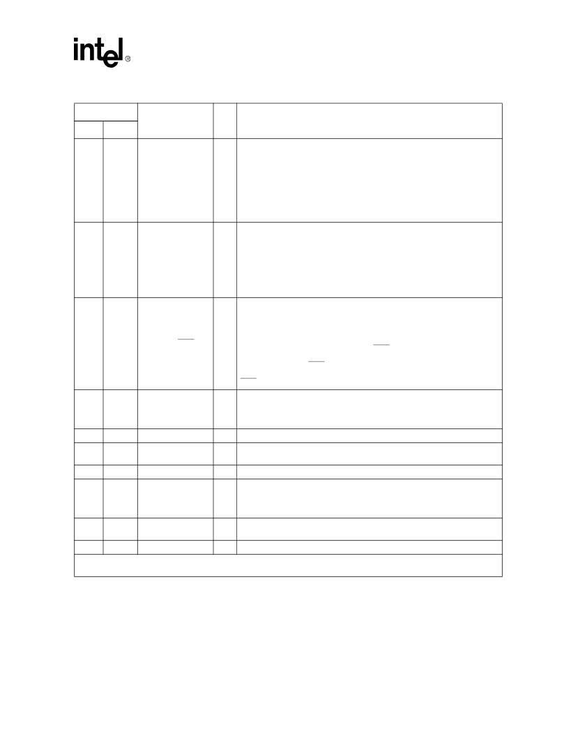
Table 3. LXT350 Signal Descriptions (Continued)
Pin #
Symbol
I/O
1
Description
PLCC
QFP
1. DI = Digital Input; DO = Digital Output; DI/O = Digital Input/Output; AI = Analog Input; AO = Analog Output.
2. Midrange is a voltage level such that 2.3 V
≤
Midrange
≤
2.7 V. Midrange may also be established by letting the pin float.
相關(guān)PDF資料 |
PDF描述 |
|---|---|
| LXT361LE | Telecommunication IC |
| LXT361PE | Telecommunication IC |
| LXT362LE | PCM TRANSCEIVER|SINGLE|T-1(DS1)|CMOS|QFP|44PIN|PLASTIC |
| LXT362PE | PCM TRANSCEIVER|SINGLE|T-1(DS1)|CMOS|LDCC|28PIN|PLASTIC |
| LXT362QE | PCM TRANSCEIVER|SINGLE|T-1(DS1)|CMOS|QFP|44PIN|PLASTIC |
相關(guān)代理商/技術(shù)參數(shù) |
參數(shù)描述 |
|---|---|
| LXT350QE | 制造商:LEVEL1 功能描述: |
| LXT351 | 制造商:INTEL 制造商全稱(chēng):Intel Corporation 功能描述:T1/E1 Short Haul Transceiver with Crystal-less Jitter Attenuation |
| LXT351PE | 制造商:INTEL 制造商全稱(chēng):Intel Corporation 功能描述:PCM TRANSCEIVER|SINGLE|CEPT PCM-30/E-1|CMOS|LDCC|28PIN|PLASTIC |
| LXT351QE | 制造商:INTEL 制造商全稱(chēng):Intel Corporation 功能描述:PCM TRANSCEIVER|SINGLE|CEPT PCM-30/E-1|CMOS|QFP|44PIN|PLASTIC |
| LXT360 | 制造商:LVL1 制造商全稱(chēng):LVL1 功能描述:Integrated T1/E1 LH/SH Transceivers for DS1/DSX-1/CSU or NTU/ISDN PRI Applications |
發(fā)布緊急采購(gòu),3分鐘左右您將得到回復(fù)。