- 您現(xiàn)在的位置:買賣IC網(wǎng) > PDF目錄366550 > AM79C961AKIW (ADVANCED MICRO DEVICES INC) PCnet⑩-ISA II Jumperless, Full Duplex Single-Chip Ethernet Controller for ISA PDF資料下載
參數(shù)資料
| 型號: | AM79C961AKIW |
| 廠商: | ADVANCED MICRO DEVICES INC |
| 元件分類: | 微控制器/微處理器 |
| 英文描述: | PCnet⑩-ISA II Jumperless, Full Duplex Single-Chip Ethernet Controller for ISA |
| 中文描述: | 2 CHANNEL(S), 10M bps, LOCAL AREA NETWORK CONTROLLER, PQFP132 |
| 封裝: | PLASTIC, QFP-132 |
| 文件頁數(shù): | 93/206頁 |
| 文件大小: | 1507K |
| 代理商: | AM79C961AKIW |
第1頁第2頁第3頁第4頁第5頁第6頁第7頁第8頁第9頁第10頁第11頁第12頁第13頁第14頁第15頁第16頁第17頁第18頁第19頁第20頁第21頁第22頁第23頁第24頁第25頁第26頁第27頁第28頁第29頁第30頁第31頁第32頁第33頁第34頁第35頁第36頁第37頁第38頁第39頁第40頁第41頁第42頁第43頁第44頁第45頁第46頁第47頁第48頁第49頁第50頁第51頁第52頁第53頁第54頁第55頁第56頁第57頁第58頁第59頁第60頁第61頁第62頁第63頁第64頁第65頁第66頁第67頁第68頁第69頁第70頁第71頁第72頁第73頁第74頁第75頁第76頁第77頁第78頁第79頁第80頁第81頁第82頁第83頁第84頁第85頁第86頁第87頁第88頁第89頁第90頁第91頁第92頁當前第93頁第94頁第95頁第96頁第97頁第98頁第99頁第100頁第101頁第102頁第103頁第104頁第105頁第106頁第107頁第108頁第109頁第110頁第111頁第112頁第113頁第114頁第115頁第116頁第117頁第118頁第119頁第120頁第121頁第122頁第123頁第124頁第125頁第126頁第127頁第128頁第129頁第130頁第131頁第132頁第133頁第134頁第135頁第136頁第137頁第138頁第139頁第140頁第141頁第142頁第143頁第144頁第145頁第146頁第147頁第148頁第149頁第150頁第151頁第152頁第153頁第154頁第155頁第156頁第157頁第158頁第159頁第160頁第161頁第162頁第163頁第164頁第165頁第166頁第167頁第168頁第169頁第170頁第171頁第172頁第173頁第174頁第175頁第176頁第177頁第178頁第179頁第180頁第181頁第182頁第183頁第184頁第185頁第186頁第187頁第188頁第189頁第190頁第191頁第192頁第193頁第194頁第195頁第196頁第197頁第198頁第199頁第200頁第201頁第202頁第203頁第204頁第205頁第206頁
Am79C961A
93
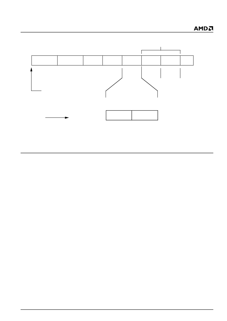
IEEE/ANSI 802.3 Frame and Length Field Transmission Order
Receive FCS Checking
Reception and checking of the received FCS is per-
formed automatically by the PCnet-ISA II controller.
Note that if the Automatic Pad Stripping feature is
enabled, the received FCS will be verified against the
value computed for the incoming bit stream including
pad characters, but it will not be passed to the host. If
a FCS error is detected, this will be reported by the
CRC bit in RMD1.
Receive Exception Conditions
Exception conditions for frame reception fall into two
distinct categories; those which are the result of normal
network operation, and those which occur due to
abnormal network and/or host related events.
Normal events which may occur and which are handled
autonomously by the PCnet-ISA II controller are basi-
cally collisions within the slot time and automatic runt
packet rejection. The PCnet-ISA II controller will ensure
that collisions which occur within 512 bit times from the
start of reception (excluding preamble) will be automat-
ically deleted from the receive FIFO with no host inter-
vention. The receive FIFO will delete any frame which
is composed of fewer than 64 bytes provided that the
Runt Packet Accept (RPA bit in CSR124) feature has
not been enabled. This criteria will be met regardless of
whether the receive frame was the first (or only) frame
in the FIFO or if the receive frame was queued behind
a previously received message.
Abnormal network conditions include:
I
FCS errors
I
Late collision
These should not occur on a correctly configured 802.3
network and will be reported if they do.
Host related receive exception conditions include
MISS, BUFF, and OFLO. These are described in the
Receive Descriptor section.
Loopback Operation
Loopback is a mode of operation intended for system
diagnostics. In this mode, the transmitter and receiver
are both operating at the same time so that the
controller receives its own transmissions. The control-
ler provides two types of internal loopback and three
types of external loopback. In internal loopback mode,
the transmitted data can be looped back to the receiver
at one of two places inside the controller without actu-
ally transmitting any data to the external network. The
receiver will move the received data to the next receive
buffer, where it can be examined by software. Alterna-
tively, external loopback causes transmissions to go
off-chip. For the AUI port, frame transmission occurs
normally and assumes that an external MAU will loop
the frame back to the chip. For the 10BASE-T port, two
external loopback options are available, both of which
require a valid link pass state and both of which trans-
mit data frames at the RJ45 interface. Selection of
these modes is defined by the TMAU_LOOPE bit in
ISACSR2. One option loops the data frame back inside
the chip, and is compatible with a
‘
live
’
network. The
Preamble
1010....1010
SYNCH
10101011
Dest.
ADDR.
Srce.
ADDR.
Length
LLC
DATA
Pad
FCS
56
Bits
8
Bits
6
Bytes
6
Bytes
2
Bytes
Bytes
4
Bytes
Most
Significant
Byte
Least
Significant
Byte
Bit
0
Bit
7
Start of Packet
at Time= 0
Increasing Time
Bit
7
Bit
0
45
–
0
Bytes
1
–
1500
Bytes
19364B-21
相關(guān)PDF資料 |
PDF描述 |
|---|---|
| AM79C961AVCW | PCnet⑩-ISA II Jumperless, Full Duplex Single-Chip Ethernet Controller for ISA |
| AM79C961AVIW | PCnet⑩-ISA II Jumperless, Full Duplex Single-Chip Ethernet Controller for ISA |
| Am79C965A | PCnet?-32 Single-Chip 32-Bit Ethernet Controller |
| AM79C970AKCW | PCnet-PCI II Single-Chip Full-Duplex Ethernet Controller for PCI Local Bus Product |
| AM79C970AKC | PCnet-PCI II Single-Chip Full-Duplex Ethernet Controller for PCI Local Bus Product |
相關(guān)代理商/技術(shù)參數(shù) |
參數(shù)描述 |
|---|---|
| AM79C961APDLUTS | 制造商:Advanced Micro Devices 功能描述: |
| AM79C961AVC | 制造商:Rochester Electronics LLC 功能描述: 制造商:Advanced Micro Devices 功能描述:LAN Node Controller, 144 Pin, TQFP |
| AM79C961AVC/W | 制造商:未知廠家 制造商全稱:未知廠家 功能描述:LAN Node Controller |
| AM79C961AVC\\W | 制造商:Rochester Electronics LLC 功能描述: |
| AM79C961AVC\W | 制造商:Rochester Electronics LLC 功能描述: |
發(fā)布緊急采購,3分鐘左右您將得到回復(fù)。