- 您現(xiàn)在的位置:買賣IC網(wǎng) > PDF目錄300038 > TMS470R1B768PGEQR (TEXAS INSTRUMENTS INC) 32-BIT, FLASH, 60 MHz, RISC MICROCONTROLLER, PQFP144 PDF資料下載
參數(shù)資料
| 型號: | TMS470R1B768PGEQR |
| 廠商: | TEXAS INSTRUMENTS INC |
| 元件分類: | 微控制器/微處理器 |
| 英文描述: | 32-BIT, FLASH, 60 MHz, RISC MICROCONTROLLER, PQFP144 |
| 封裝: | PLASTIC, LQFP-144 |
| 文件頁數(shù): | 47/49頁 |
| 文件大?。?/td> | 552K |
| 代理商: | TMS470R1B768PGEQR |
第1頁第2頁第3頁第4頁第5頁第6頁第7頁第8頁第9頁第10頁第11頁第12頁第13頁第14頁第15頁第16頁第17頁第18頁第19頁第20頁第21頁第22頁第23頁第24頁第25頁第26頁第27頁第28頁第29頁第30頁第31頁第32頁第33頁第34頁第35頁第36頁第37頁第38頁第39頁第40頁第41頁第42頁第43頁第44頁第45頁第46頁當前第47頁第48頁第49頁
www.ti.com ......................................................................................................................................................... SPNS108B – AUGUST 2005 – REVISED MAY 2008
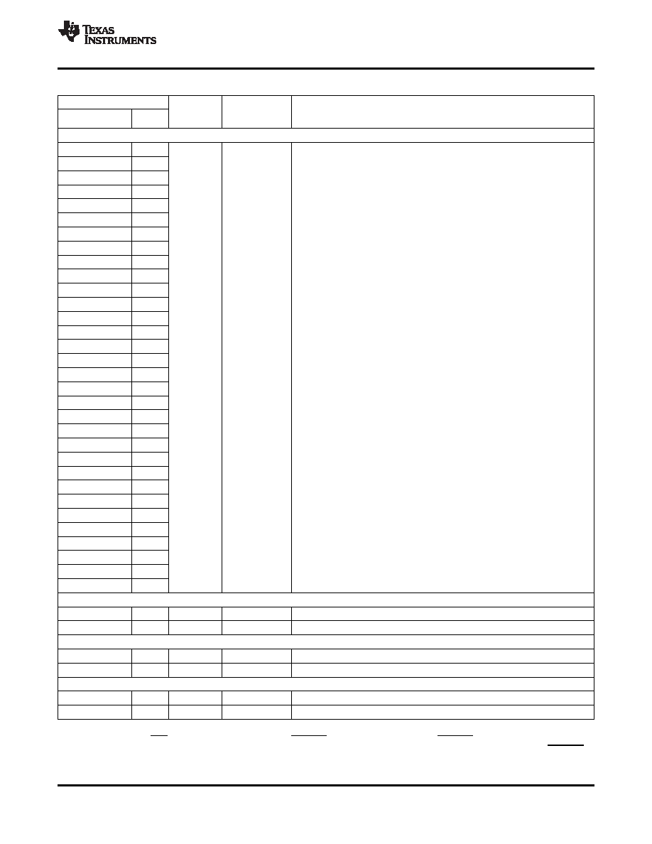
Table 2. Terminal Functions
TERMINAL
INTERNAL
TYPE(1)(2)
PULLUP/
DESCRIPTION
NAME
NO.
PULLDOWN(3)
HIGH-END TIMER (HET)
HET[0]
129
HET[1]
130
HET[2]
137
HET[3]
138
HET[4]
139
HET[5]
140
HET[6]
141
HET[7]
142
HET[8]
79
HET[9]
80
HET[10]
29
HET[11]
28
The B768 device has both the logic and registers for a full 32-I/O HET
HET[12]
27
implemented and all 32 pins are available externally.
HET[13]
26
Timer input capture or output compare. The HET[31:0] applicable pins can be
programmed as general-purpose input/output (GIO) pins. HET[23:0] are
HET[14]
25
high-resolution pins and HET[31:24] are standard-resolution pins.
HET[15]
24
The high-resolution (HR) SHARE feature allows even HR pins to share the
3.3-V I/O
IPD (20 A)
HET[16]
23
next higher odd-numbered HR pin structures. This HR sharing is independent
of whether or not the odd pin is available externally. If an odd pin is available
HET[17]
22
externally and shared, then the odd pin can only be used as a
HET[18]
71
general-purpose I/O. For more information on HR SHARE, see the
TMS470R1x High-End Timer (HET) Reference Guide (literature number
HET[19]
70
SPNU199).
HET[20]
69
HET[21]
68
HET[22]
67
HET[23]
123
HET[24]
51
HET[25]
124
HET[26]
125
HET[27]
126
HET[28]
47
HET[29]
48
HET[30]
49
HET[31]
50
HIGH-END CAN CONTROLLER 1 (HECC1)
CAN1HTX
88
3.3-V I/O
IPU (20 A)
HECC1 transmit pin or GIO pin
CAN1HRX
87
3.3-V I/O
HECC1 receive pin or GIO pin
HIGH-END CAN CONTROLLER 2 (HECC2)
CAN2HTX
56
3.3-V I/O
IPU (20 A)
HECC2 transmit pin or GIO pin
CAN2HRX
57
3.3-V I/O
HECC2 receive pin or GIO pin
HIGH-END CAN CONTROLLER 3 (HECC3)
CAN3HTX
78
3.3 V I/O
IPU (20 A)
HECC3 transmit pin or GIO pin
CAN3HRX
77
3.3 V I/O
HECC3 receive pin or GIO pin
(1)
I = input, O = output, PWR = power, GND = ground, REF = reference voltage, NC = no connect
(2)
All I/O pins, except RST , are configured as inputs while PORRST is low and immediately after PORRST goes high.
(3)
IPD = internal pulldown, IPU = internal pullup (all internal pullups and pulldowns are active on input pins, independent of the PORRST
state.)
Copyright 2005–2008, Texas Instruments Incorporated
7
Product Folder Link(s): TMS470R1B768
相關(guān)PDF資料 |
PDF描述 |
|---|---|
| TMS4C1050-4DJL | 256K X 4 OTHER FIFO, PDSO20 |
| TMS4C1050-3NL | 256K X 4 OTHER FIFO, PDIP16 |
| TMS570LS10216ASZWTQR | 32-BIT, FLASH, 160 MHz, RISC MICROCONTROLLER, PBGA337 |
| TMX320DM642GNZ500 | 64-BIT, 75.19 MHz, OTHER DSP, PBGA548 |
| TN4002PM | 10 MHz - 500 MHz RF/MICROWAVE WIDE BAND LOW POWER AMPLIFIER |
相關(guān)代理商/技術(shù)參數(shù) |
參數(shù)描述 |
|---|---|
| TMS470R1B768PGET | 功能描述:ARM微控制器 - MCU 60mhz / 768k Flash RoHS:否 制造商:STMicroelectronics 核心:ARM Cortex M4F 處理器系列:STM32F373xx 數(shù)據(jù)總線寬度:32 bit 最大時鐘頻率:72 MHz 程序存儲器大小:256 KB 數(shù)據(jù) RAM 大小:32 KB 片上 ADC:Yes 工作電源電壓:1.65 V to 3.6 V, 2 V to 3.6 V, 2.2 V to 3.6 V 工作溫度范圍:- 40 C to + 85 C 封裝 / 箱體:LQFP-48 安裝風格:SMD/SMT |
| TMS470R1F316PZQ | 制造商:Texas Instruments 功能描述: |
| TMS470R1F354PNQ | 制造商:Texas Instruments 功能描述: |
| TMS470R1F366APZQ | 制造商:Texas Instruments 功能描述: |
| TMS470R1F369APGEQ | 制造商:Texas Instruments 功能描述: |
發(fā)布緊急采購,3分鐘左右您將得到回復(fù)。