- 您現(xiàn)在的位置:買賣IC網(wǎng) > PDF目錄378661 > MC44011FN (MOTOROLA INC) BUS CONTROLLED MULTISTANDARD VIDEO PROCESSOR PDF資料下載
參數(shù)資料
| 型號: | MC44011FN |
| 廠商: | MOTOROLA INC |
| 元件分類: | 消費家電 |
| 英文描述: | BUS CONTROLLED MULTISTANDARD VIDEO PROCESSOR |
| 中文描述: | SPECIALTY CONSUMER CIRCUIT, PQCC44 |
| 封裝: | PLASTIC, LCC-44 |
| 文件頁數(shù): | 41/52頁 |
| 文件大小: | 835K |
| 代理商: | MC44011FN |
第1頁第2頁第3頁第4頁第5頁第6頁第7頁第8頁第9頁第10頁第11頁第12頁第13頁第14頁第15頁第16頁第17頁第18頁第19頁第20頁第21頁第22頁第23頁第24頁第25頁第26頁第27頁第28頁第29頁第30頁第31頁第32頁第33頁第34頁第35頁第36頁第37頁第38頁第39頁第40頁當前第41頁第42頁第43頁第44頁第45頁第46頁第47頁第48頁第49頁第50頁第51頁第52頁
MC44011
41
MOTOROLA ANALOG IC DEVICE DATA
Table 20. Color Standard Selection Table
Flags
Bit Settings
#14
<576 Lines
#23
ACC Active
#24
PAL Signal
Crystal
SSA
($7C–6)
SSB
($7D–6)
SSC
($7C–7)
System
X
0
X
Either
1
1
0
Color Kill
0
1
0
Either
1
1
0
Color Kill
0
1
1
17.7 MHz
0
1
0
PAL
1
1
0
14.3 MHz
1
0
0
NTSC
1
1
1
(Note 1)
0
1
0
PAL–M
NOTES:
1.PAL–M, used in Brazil and other South American countries, can be decoded by the MC44011, but requires a 14.3024 MHz crystal.
2.SSD ($7A–6) is always set to 0.
MISCELLANEOUS APPLICATIONS INFORMATION
Use of the MC44140 Delay Line
The MC44140 delay line is generally required if PAL
signals are to be decoded, so as to average out the
line–by–line color information associated with PAL color
decoding. If the same single PAL video source is always used
in a particular application, the delay line can be eliminated,
and any slight phase errors can be corrected with the DAC of
register $79–5/0. If, however, various video sources can be
used, and/or if the video signal is less than broadcast quality,
it is recommended the MC44140 delay line be included.
The MC44140 acts on the color difference signals before
they enter the color difference stage of the MC44011. It will,
however, pass NTSC signals through without modifications.
The MC44011 uses the System Select output (Pin 34) to
indicate to the delay line which signals are being processed.
The System Select voltage is set when the color decoder is
set with Bits SSA, SSB, SSC, SSD. The Sandcastle output
(Pin 35) provides the horizontal timing signals to the delay
line. In addition, the MC44140 uses the crystal frequency for
the internal counters.
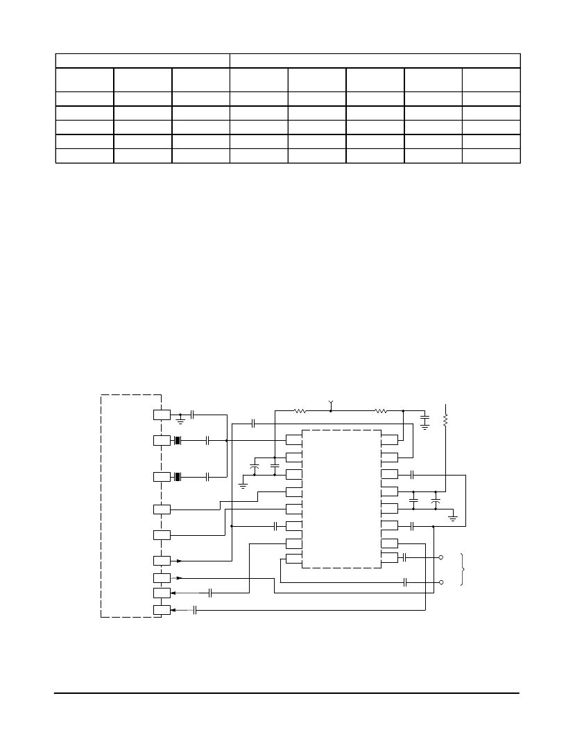
The MC44140 is inserted into the circuit between the Color
Difference outputs and inputs of the MC44011. In addition,
the MC44140 provides pins (Pins 8,9) for inserting an
alternate source of color difference signals to the MC44011
by setting the System Select to external (Bit $7C–7 = 1). See
Figure 44 for a suggested circuit.
If only NTSC signals are to be processed by the MC44011,
the MC44140 is not needed. In this case, connect Pin 42 to
Pin 31 with a 0.1
μ
F capacitor, and similarly connect Pin 41 to
Pin 30.
MC44140
R–Y
B–Y
0.01
0.01
0.1
1.0
0.02
47
5.0
0.01
68 k
5.0
0.1
0.02
MC44011
17.7 MHz
22 pF
22 pF
120 pF
10
1.0
0.1
0.1
B–Y In
R–Y In
B–Y Out
R–Y Out
Sys Sel
SandC
Xtal 2
Xtal 1
Gnd
Ext B–Y
B–Y Out
B–Y In
Gnd
VDD
B–Y In
R–Y In
Bias
Ext R–Y
R–Y Out
R–Y In
Sys Sel
SandC
Gnd
VDDA
Clk
8
7
6
5
4
3
2
1
14.3 MHz
Figure 44. Incorporating the MC44140 Delay Line
39
38
36
35
30
31
41
42
34
Alternate
Inputs
22
16
15
14
13
12
11
10
9
22
相關PDF資料 |
PDF描述 |
|---|---|
| MC44871DTB | PLL TUNING CIRCUIT WITH HIGH SPEED I2C BUS AND 30 V TUNING SUPPLY |
| MC68705P3CS | 8-Bit EPROM Microcomputer Unit |
| MC68705P3 | 8-Bit EPROM Microcomputer Unit |
| MC68705P3S | 8-Bit EPROM Microcomputer Unit |
| MC68705R3 | 8-Bit EPROM Microcontroller Unit |
相關代理商/技術參數(shù) |
參數(shù)描述 |
|---|---|
| MC4403 | 制造商:SHENZHENFREESCALE 制造商全稱:ShenZhen FreesCale Electronics. Co., Ltd 功能描述:P-Channel 20-V (D-S) MOSFET High performance trench technology |
| MC44030FTB | 制造商:MOTOROLA 制造商全稱:Motorola, Inc 功能描述:MULTISTANDARD VIDEO SIGNAL PROCESSOR WITH INTEGRATED CHROMA DELAY LINE |
| MC44030P | 制造商:MOTOROLA 制造商全稱:Motorola, Inc 功能描述:MULTISTANDARD VIDEO SIGNAL PROCESSOR WITH INTEGRATED CHROMA DELAY LINE |
| MC44035FTB | 制造商:MOTOROLA 制造商全稱:Motorola, Inc 功能描述:MULTISTANDARD VIDEO SIGNAL PROCESSOR WITH INTEGRATED CHROMA DELAY LINE |
| MC44035P | 制造商:MOTOROLA 制造商全稱:Motorola, Inc 功能描述:MULTISTANDARD VIDEO SIGNAL PROCESSOR WITH INTEGRATED CHROMA DELAY LINE |
發(fā)布緊急采購,3分鐘左右您將得到回復。