- 您現(xiàn)在的位置:買(mǎi)賣(mài)IC網(wǎng) > PDF目錄378661 > MC44011FN (MOTOROLA INC) BUS CONTROLLED MULTISTANDARD VIDEO PROCESSOR PDF資料下載
參數(shù)資料
| 型號(hào): | MC44011FN |
| 廠商: | MOTOROLA INC |
| 元件分類: | 消費(fèi)家電 |
| 英文描述: | BUS CONTROLLED MULTISTANDARD VIDEO PROCESSOR |
| 中文描述: | SPECIALTY CONSUMER CIRCUIT, PQCC44 |
| 封裝: | PLASTIC, LCC-44 |
| 文件頁(yè)數(shù): | 11/52頁(yè) |
| 文件大小: | 835K |
| 代理商: | MC44011FN |
第1頁(yè)第2頁(yè)第3頁(yè)第4頁(yè)第5頁(yè)第6頁(yè)第7頁(yè)第8頁(yè)第9頁(yè)第10頁(yè)當(dāng)前第11頁(yè)第12頁(yè)第13頁(yè)第14頁(yè)第15頁(yè)第16頁(yè)第17頁(yè)第18頁(yè)第19頁(yè)第20頁(yè)第21頁(yè)第22頁(yè)第23頁(yè)第24頁(yè)第25頁(yè)第26頁(yè)第27頁(yè)第28頁(yè)第29頁(yè)第30頁(yè)第31頁(yè)第32頁(yè)第33頁(yè)第34頁(yè)第35頁(yè)第36頁(yè)第37頁(yè)第38頁(yè)第39頁(yè)第40頁(yè)第41頁(yè)第42頁(yè)第43頁(yè)第44頁(yè)第45頁(yè)第46頁(yè)第47頁(yè)第48頁(yè)第49頁(yè)第50頁(yè)第51頁(yè)第52頁(yè)
MC44011
11
MOTOROLA ANALOG IC DEVICE DATA
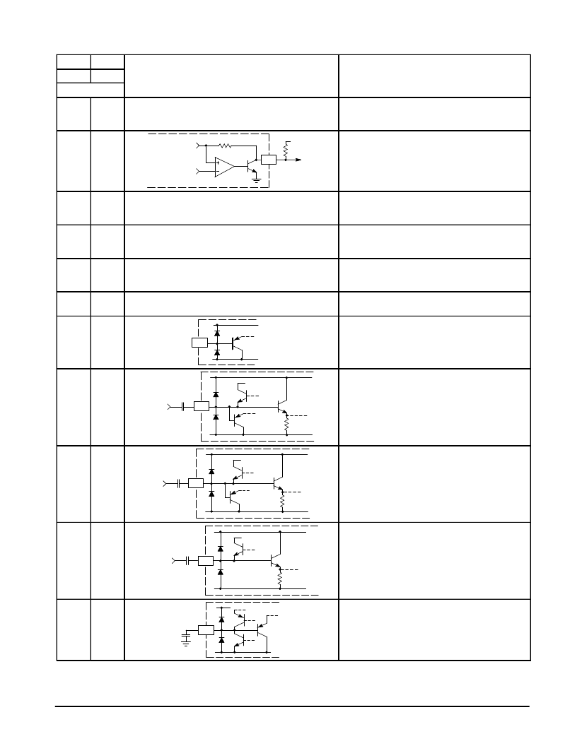
PIN FUNCTION DESCRIPTION (continued)
FB
FN
QFP
Description
(Pin numbers refer to PLCC package)
(Pin numbers refer to PLCC package)
PLCC
Pin
Representative Circuitry
13
19
(See power distribution diagram at the end of this section.)
VCC3
– A 5.0 V supply (
±
5%), for the high frequency
PLL #2. Decoupling must be provided from this pin to
Pin 17. Ripple on this pin will affect pixel clock jitter.
14
20
Output
5.0 V
390
36 k
Brightness
Color
& Gain
20
R/V Output
– Red (in RGB mode), or R–Y (in YUV
mode), output from the color difference stage. A
pull–up (390
) to 5.0 V is required. Blank level is
≈
1.4 Vdc. Maximum amplitude is
≈
3.0 Vpp,
black–to–white.
15
21
(Same as Pin 20)
G/Y Output
– Green (in RGB mode), or Y (in YUV
mode), output from the color difference stage (same
as Pin 20).
16
22
(Same as Pin 20)
B/U Output
– Blue (in RGB mode), or B–Y (in YUV
mode), output from the color difference stage (same
as Pin 20).
17
23
(See power distribution diagram at the end of this section.)
VCC2
– A 5.0 V supply (
±
5%), for the color difference
stage. Decoupling must be provided from this pin to
Pin 24.
18
24
(See power distribution diagram at the end of this section.)
Gnd2
– Ground for the color difference stage. Signals
at Pins 20 to 31 should be referenced to this pin.
19
25
25
FC
– Fast Commutate switch. Taking this pin high
(TTL level) connects the RGB inputs (Pins 26 to 28)
to the RGB outputs (Pins 20 to 22), permitting an
overlay function. The switch can be disabled in
software (Bit $80–7).
20, 21,
22
26, 27,
28
100 k
Vref
R, G, B
Inputs
Blue (26), Green (27), Red (28) Inputs
– Inputs to
the color difference stage. Designed to accept
standard analog video levels, these input pins have a
clamp and sync separator. They are selected with
Pin 25 or in software (Bit $80–7).
23
29
Y2
Input
100 k
Vref
29
Y2 Input
– Luma #2/Composite sync input. This
luma input to the color difference stage is used in
conjunction with auxiliary color difference inputs,
and/or as a sync input. Clamp and sync separator
are provided.
24, 25
30, 31
100 k
Vref
R–Y, B–Y
Inputs
B–Y (30), R–Y (31) Inputs
– Inputs to the color
difference stage. Designed for standard color
difference levels, these inputs can be capacitor
coupled from the color difference outputs, from a delay
line, or an auxiliary signal source. Input clamp is
provided.
26
32
0.47
32
Y1 Clamp
– A 0.47
μ
F capacitor at this pin provides
clamping for the Luma #1 output.
相關(guān)PDF資料 |
PDF描述 |
|---|---|
| MC44871DTB | PLL TUNING CIRCUIT WITH HIGH SPEED I2C BUS AND 30 V TUNING SUPPLY |
| MC68705P3CS | 8-Bit EPROM Microcomputer Unit |
| MC68705P3 | 8-Bit EPROM Microcomputer Unit |
| MC68705P3S | 8-Bit EPROM Microcomputer Unit |
| MC68705R3 | 8-Bit EPROM Microcontroller Unit |
相關(guān)代理商/技術(shù)參數(shù) |
參數(shù)描述 |
|---|---|
| MC4403 | 制造商:SHENZHENFREESCALE 制造商全稱:ShenZhen FreesCale Electronics. Co., Ltd 功能描述:P-Channel 20-V (D-S) MOSFET High performance trench technology |
| MC44030FTB | 制造商:MOTOROLA 制造商全稱:Motorola, Inc 功能描述:MULTISTANDARD VIDEO SIGNAL PROCESSOR WITH INTEGRATED CHROMA DELAY LINE |
| MC44030P | 制造商:MOTOROLA 制造商全稱:Motorola, Inc 功能描述:MULTISTANDARD VIDEO SIGNAL PROCESSOR WITH INTEGRATED CHROMA DELAY LINE |
| MC44035FTB | 制造商:MOTOROLA 制造商全稱:Motorola, Inc 功能描述:MULTISTANDARD VIDEO SIGNAL PROCESSOR WITH INTEGRATED CHROMA DELAY LINE |
| MC44035P | 制造商:MOTOROLA 制造商全稱:Motorola, Inc 功能描述:MULTISTANDARD VIDEO SIGNAL PROCESSOR WITH INTEGRATED CHROMA DELAY LINE |
發(fā)布緊急采購(gòu),3分鐘左右您將得到回復(fù)。