- 您現(xiàn)在的位置:買賣IC網(wǎng) > PDF目錄378661 > MC44011FN (MOTOROLA INC) BUS CONTROLLED MULTISTANDARD VIDEO PROCESSOR PDF資料下載
參數(shù)資料
| 型號(hào): | MC44011FN |
| 廠商: | MOTOROLA INC |
| 元件分類: | 消費(fèi)家電 |
| 英文描述: | BUS CONTROLLED MULTISTANDARD VIDEO PROCESSOR |
| 中文描述: | SPECIALTY CONSUMER CIRCUIT, PQCC44 |
| 封裝: | PLASTIC, LCC-44 |
| 文件頁數(shù): | 25/52頁 |
| 文件大小: | 835K |
| 代理商: | MC44011FN |
第1頁第2頁第3頁第4頁第5頁第6頁第7頁第8頁第9頁第10頁第11頁第12頁第13頁第14頁第15頁第16頁第17頁第18頁第19頁第20頁第21頁第22頁第23頁第24頁當(dāng)前第25頁第26頁第27頁第28頁第29頁第30頁第31頁第32頁第33頁第34頁第35頁第36頁第37頁第38頁第39頁第40頁第41頁第42頁第43頁第44頁第45頁第46頁第47頁第48頁第49頁第50頁第51頁第52頁
MC44011
25
MOTOROLA ANALOG IC DEVICE DATA
FUNCTIONAL DESCRIPTION
Introduction
The MC44011, a member of the MC44000 Chroma 4
family, is a composite video decoder which has been tailored
for applications involving multimedia, picture–in–picture, and
frame storage (although not limited to those applications).
The first stage of the MC44011 provides color difference
signals (R–Y, B–Y, and Y) from one of two (selectable)
composite video inputs, which are designed to receive PAL,
NTSC, and S–VHS (Y,C) signals. The second stage provides
either RGB or YUV outputs from the first stage’s signals, or
from a separate (internally selectable) set of RGB inputs,
permitting an overlay function to be performed. Adjustments
can be made to saturation; hue; brightness; contrast;
brightness balance; contrast balance; U and V bias;
subcarrier phase; and color difference gain ratio.
The above mentioned video decoding sections provide the
necessary luma/delay function, as well as all necessary
filters for sound traps, luma/chroma separation, luma
peaking, and subcarrier rejection. External tank circuits and
luma delay lines are not needed. For PAL applications, the
MC44140 chroma delay line provides the necessary
line–by–line corrections to the color difference signals
required by that system.
The MC44011 provides a pixel clock to set the sampling
rate of external A/D converters. This pixel clock, and other
horizontal frequency related output signals, are
phase–locked to the incoming sync. The VCO’s gain is
adjustable for optimum performance. The MC44011 also
provides vertical sync and field identification (Field 1, Field 2)
outputs.
Selection of the various inputs, outputs, and functions, as
well as the adjustments, is done by means of a two–wire I2C
interface. The basic procedure requires the microprocessor
system to read the internal flags of the MC44011, and then
set the internal registers appropriately. This I2C
interface
eliminates the need for manual controls (potentiometers) and
external switches. All of the external components for the
MC44011, except for the two crystals, are standard value
resistors and capacitors, and can be non–precision.
(The DACs mentioned n he ollowing description are 6–bits wide. The
settings mentioned for them are given in decimal values of 00 to 63.
These are not hex values.)
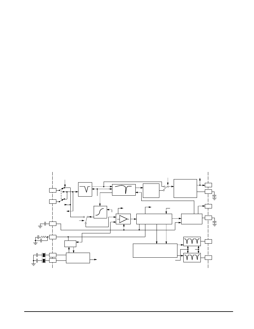
PAL/NTSC/S–VHS Decoder
A block diagram of this decoder section is shown in
Figure 35. This section’s function is to take the incoming
composite video (at Pins 1 or 3), separate it into luma and
chroma information, determine if the signal is PAL or NTSC
(for the flags), and then provide color difference and luma
signals at the outputs. If the input is S–VHS, the luma/chroma
separation is bypassed, but the other functions are still
in effect.
Sep
41
42
C
C
ACC
C
Sound
Trap
($77–6)
Chroma
Filter
Blanking
Color System
($7C–7,6; $7D–6)
Flag 24
(PAL)
Flag 23
(ACC Active)
Chroma Trap and
Luma Peaking
($7D–7; $7E–7,6)
($77–7)
4.4/4.8/5.2
5.5/6.0/6.5 MHz
($7B–7,6)
To Color
Diff Stage
Y1 Out
Y1 Clamp
System
Select
Ident
Filter
R–Y Out
B–Y Out
3.6/7.2/28.6/4.4/
8.8/35.4 MHz Notch
Switches shown with control bits = 0.
Crystal Select
($7A–7)
Phase Adjust ($79–5/0)
Xtal 2
Xtal 1
Chroma PLL Filter
ACC Filter
Comp
Video 2
Comp
Video 1
Select
($88–7)
PLL
Saturation ($87–5/0)
Hue ($88–5/0)
Color Balance ($78–5/0)
Oscillator
Ident
Circuit
295/244 ns
Luma
Delay
Adjustable
Luma Delay
($7F–7,6; $80–6)
32
33
34
43
36
38
44
2
3
1
PAL/NTSC
Decoder
Figure 35. PAL/NTSC/S–VHS Decoder Block Diagram
3.6/7.2/28.6/4.4/
8.8/35.4 MHz Notch
Sync
To
相關(guān)PDF資料 |
PDF描述 |
|---|---|
| MC44871DTB | PLL TUNING CIRCUIT WITH HIGH SPEED I2C BUS AND 30 V TUNING SUPPLY |
| MC68705P3CS | 8-Bit EPROM Microcomputer Unit |
| MC68705P3 | 8-Bit EPROM Microcomputer Unit |
| MC68705P3S | 8-Bit EPROM Microcomputer Unit |
| MC68705R3 | 8-Bit EPROM Microcontroller Unit |
相關(guān)代理商/技術(shù)參數(shù) |
參數(shù)描述 |
|---|---|
| MC4403 | 制造商:SHENZHENFREESCALE 制造商全稱:ShenZhen FreesCale Electronics. Co., Ltd 功能描述:P-Channel 20-V (D-S) MOSFET High performance trench technology |
| MC44030FTB | 制造商:MOTOROLA 制造商全稱:Motorola, Inc 功能描述:MULTISTANDARD VIDEO SIGNAL PROCESSOR WITH INTEGRATED CHROMA DELAY LINE |
| MC44030P | 制造商:MOTOROLA 制造商全稱:Motorola, Inc 功能描述:MULTISTANDARD VIDEO SIGNAL PROCESSOR WITH INTEGRATED CHROMA DELAY LINE |
| MC44035FTB | 制造商:MOTOROLA 制造商全稱:Motorola, Inc 功能描述:MULTISTANDARD VIDEO SIGNAL PROCESSOR WITH INTEGRATED CHROMA DELAY LINE |
| MC44035P | 制造商:MOTOROLA 制造商全稱:Motorola, Inc 功能描述:MULTISTANDARD VIDEO SIGNAL PROCESSOR WITH INTEGRATED CHROMA DELAY LINE |
發(fā)布緊急采購,3分鐘左右您將得到回復(fù)。