- 您現(xiàn)在的位置:買賣IC網(wǎng) > PDF目錄67775 > M44C092 (ATMEL CORP) 4-BIT, MROM, 4 MHz, MICROCONTROLLER, PDSO20 PDF資料下載
參數(shù)資料
| 型號: | M44C092 |
| 廠商: | ATMEL CORP |
| 元件分類: | 微控制器/微處理器 |
| 英文描述: | 4-BIT, MROM, 4 MHz, MICROCONTROLLER, PDSO20 |
| 封裝: | SSO-20 |
| 文件頁數(shù): | 70/84頁 |
| 文件大?。?/td> | 643K |
| 代理商: | M44C092 |
第1頁第2頁第3頁第4頁第5頁第6頁第7頁第8頁第9頁第10頁第11頁第12頁第13頁第14頁第15頁第16頁第17頁第18頁第19頁第20頁第21頁第22頁第23頁第24頁第25頁第26頁第27頁第28頁第29頁第30頁第31頁第32頁第33頁第34頁第35頁第36頁第37頁第38頁第39頁第40頁第41頁第42頁第43頁第44頁第45頁第46頁第47頁第48頁第49頁第50頁第51頁第52頁第53頁第54頁第55頁第56頁第57頁第58頁第59頁第60頁第61頁第62頁第63頁第64頁第65頁第66頁第67頁第68頁第69頁當(dāng)前第70頁第71頁第72頁第73頁第74頁第75頁第76頁第77頁第78頁第79頁第80頁第81頁第82頁第83頁第84頁
M44C892
M44C092
Rev. A5, 14-Dec-01
72 (84)
4.1.1
Serial Interface
The U505M has an I2C-like two-wire serial interface to
the microcontroller for read and write accesses to the
EEPROM. The U505M is considered to be a slave in all
these applications. That means, the controller has to be
the master that initiates the data transfer and provides the
clock for transmit and receive operations.
The serial interface is controlled by the M44C892
microcontroller which generates the serial clock and
controls the access via the SCL-line and SDA-line. SCL
is used to clock the data into and out of the device. SDA
is a bidirectional line that is used to transfer data into and
out of the device. The following protocol is used for the
data transfers.
Serial Protocol
D Data states on the SDA-line changing only while SCL
is low.
D Changes on the SDA-line while SCL is high are
interpreted as START or STOP condition.
D A START condition is defined as high to low transi-
tion on the SDA-line while the SCL-line is high.
D A STOP condition is defined as low to high transition
on the SDA-line while the SCL-line is high.
D Each data transfer must be initialized with a START
condition and terminated with a STOP condition. The
START condition wakes the device from standby
mode and the STOP condition returns the device to
standby mode.
D A receiving device generates an acknowledge (A)
after the reception of each byte. This requires an
additional clock pulse, generated by the master. If the
reception was successful the receiving master or slave
device pulls down the SDA-line during that clock
cycle. If an acknowledge is not detected (N) by the
interface in transmit mode, it will terminate further
data transmissions and go into receive mode. A master
device must finish its read operation by a non-ac-
knowledge and then send a stop condition to bring the
device into a known state.
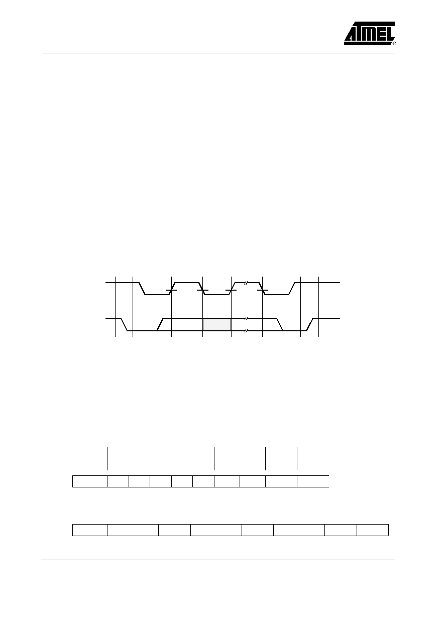
Start
condition
Data
valid
Data
change
Data/
acknowledge
valid
Stop
condition
13884
SCL
SDA
Stand
by
Stand-
by
Figure 88. I2C protocol
D Before the START condition and after the STOP
condition the device is in stand-by mode and the SDA
line is switched as input with pull-up resistor.
D The control byte that follows the START condition de-
termines the following operation. It consists of the
5-bit row address, 2 mode control bits and the READ
/ NWRITE bit that is used to control the direction of
the following transfer. A ”0” defines a write access
and a ”1” a read access.
D Control byte format:
EEPROM address
Mode control
bits
Read/
NWrite
Start
A4
A3
A2
A1
A0
C1
C0
R/NW
Ackn
D Control byte format:
Start
Control byte
Ackn
Data byte
Ackn
Data byte
Ackn
Stop
相關(guān)PDF資料 |
PDF描述 |
|---|---|
| M48T129Y-85PM1 | 0 TIMER(S), REAL TIME CLOCK, DMA32 |
| M48T129V-70PM1 | 0 TIMER(S), REAL TIME CLOCK, PDIP32 |
| M48T251Y-70PM1 | 0 TIMER(S), REAL TIME CLOCK, PDIP32 |
| M48T35Y-70PC6 | 0 TIMER(S), REAL TIME CLOCK, PDIP28 |
| M5M80C85AP-2 | 8-BIT, 5 MHz, MICROPROCESSOR, PDIP40 |
相關(guān)代理商/技術(shù)參數(shù) |
參數(shù)描述 |
|---|---|
| M44C890 | 制造商:ATMEL 制造商全稱:ATMEL Corporation 功能描述:Low-Current Microcontroller for Wireless Communication |
| M44C890-H | 制造商:ATMEL 制造商全稱:ATMEL Corporation 功能描述:Low-Current Microcontroller for Wireless Communication |
| M44S05K4F1 | 功能描述:汽車連接器 MX44 Terminals RoHS:否 制造商:Amphenol SINE Systems 產(chǎn)品:Contacts 系列:ATP 位置數(shù)量: 型式:Female 安裝風(fēng)格: 端接類型: 觸點電鍍:Nickel |
| M44T332538880MHZ | 制造商:MEC 功能描述: |
| M44T3338880MHZ | 制造商:MEC 功能描述: |
發(fā)布緊急采購,3分鐘左右您將得到回復(fù)。